Routing
As a semi-modular synthesizer Massive X allows you to edit its internal signal path via the Routing page.
Massive X is a semi-modular synthesizer with an open architecture. This means you can freely arrange and connect its modules to facilitate a wide range of different synthesis techniques, giving you the freedom to design and explore sounds without constraints.
You can use and combine techniques like wavetable synthesis, phase modulation (PM, also called FM or frequency modulation), subtractive synthesis, physical modeling, and various types of waveshaping, or distortion. Modules are arranged and connected on the Routing page. Here you can combine all of Massive X's sound generators and processors to create your sound.
Tip
From the Settings menu in the Header you can quickly load the preset Init - Massive X, which offers a pre-configured routing as shown in the screenshot below (based on subtractive synthesis with Wavetable oscillators). This way you can immediately start creating sounds without having to make connections.
Routing page overview
The following overview shows the Routing page's two main areas, the Polyphonic Area and the Monophonic Area. The Polyphonic Area is used to define the signal path that is processed independently for every single voice you play. The Monophonic Area contains three Stereo Effects that are globally applied to the sum of all polyphonic voices.
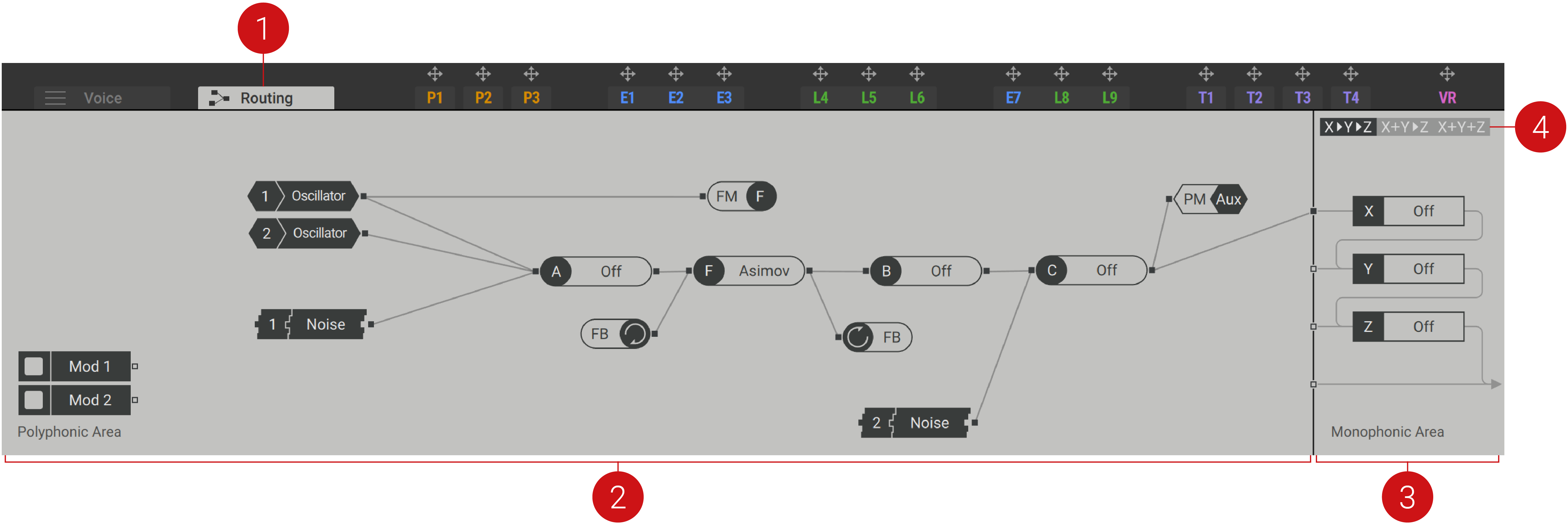
Routing Tab: Opens the Routing page in the editor.
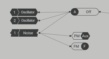
Polyphonic Area: Contains modules that you can use to define the signal path of the polyphonic voices. In order to complete the signal path, one or more module outputs need to be connected to the inputs of the Monophonic Area (2). The following modules can be found in the Polyphonic Area:
Generators and processors: The Oscillators, Noise sources, the Filter, and the Insert Effects are available in the Polyphonic Area. Black modules represent generators, gray modules represent processors. The icons shown on the modules can also be found on the corresponding module panel. For more information, refer to Generators and processors.
PM Aux bus: Makes the phase modulation inputs of the Oscillators accessible in the routing. This way you can use any source in the signal path to apply phase modulation to the Wavetable oscillators and experiment with noise, feedback, and effects in this application. For more information, refer to PM Aux bus.
FB (Feedback) loop: Makes the global feedback loop accessible in the routing. This way you can create a polyphonic feedback loop around modules to add chaotic and non-linear behavior. This feature is also useful for physical modeling sounds, especially when combined with the Comb filter. For more information, refer to Feedback loop.
Mod (Modulation) modules: Any modulation source can be assigned to the Modulation modules by dragging and dropping. This way you can use the modulation sources as generators in the signal path. For example, you can use the Switcher LFO in OSC mode as an additional oscillator, or the Exciter Envelope as an exciter for the Comb filter. For more information, refer to Modulation modules.
Monophonic Area: Sums the polyphonic voices and applies the three Stereo Effects X, Y, and Z before sending the output signal to the host. The Monophonic Area provides four inputs, one for each Stereo Effect as well as a single input that is directly sent to the host. For more information on the Stereo Effects, refer to Stereo effects.
Routing Options: Three different routing options define the order of the effects in the signal path: X > Y > Z chains the three effects, X + Y > Z sends the sum of the X and Y effects to the Z effect, and X + Y + Z sums all three effects.
Generators and processors
The generators and processors available in the Polyphonic Area of the Routing page are the basic components you can use to build your sound. They consist of the Oscillators, Noise sources, the Filter, and the Insert Effects.
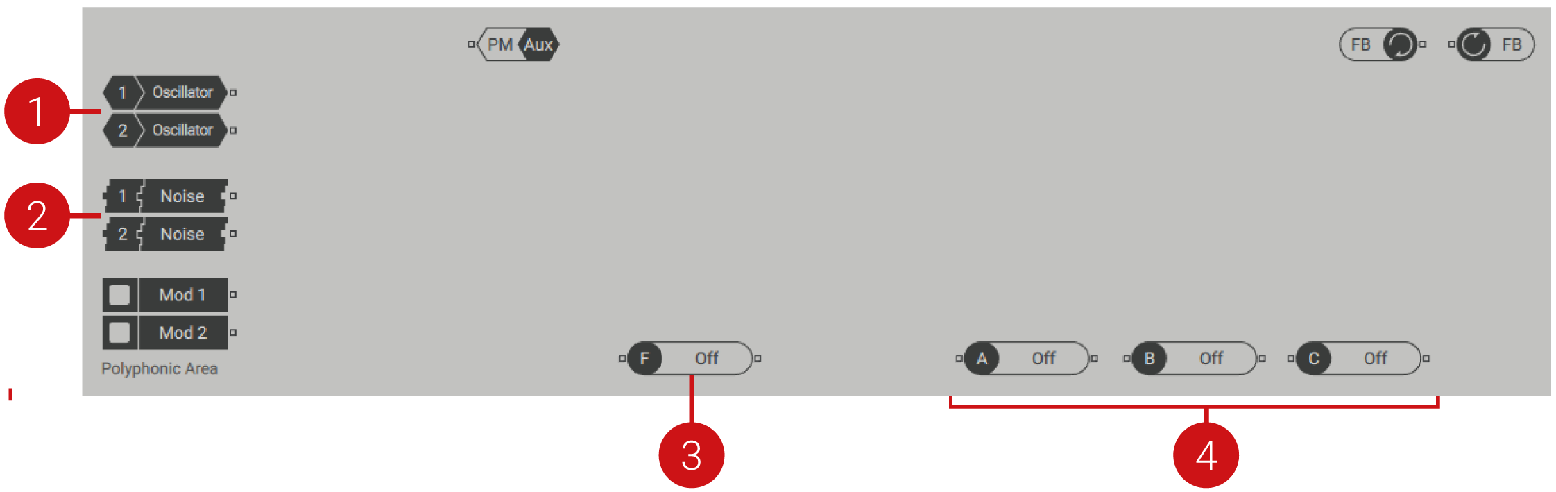
Oscillators: The Wavetable oscillators 1 and 2 are generators that each feature a single output. They can be connected to the processors and buses in the Polyphonic Area, or directly to an input of the Monophonic Area. For more information about the Oscillators, refer to Wavetable oscillators.
Noise sources: The Noise sources 1 and 2 are generators that each feature a single output. They can be connected to the processors and buses in the Polyphonic Area, or directly to an input of the Monophonic Area. For more information about the Noise sources, refer to Noise.
Filter: The Filter is a processor that features a single input and a single output. It can be connected to the generators, processors, and buses in the Polyphonic Area, or directly to an input of the Monophonic Area. The Filter types Asimov, Blue Monark, Groian, Scanner feature a special FM bus in the routing.
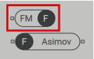
You can connect any source in the signal path here to apply audio rate modulation to the filter frequency, also called filter FM (frequency modulation). Filter FM produces rich harmonics and distortion effects. For more information about the Filter, refer to Filter.
Insert Effects: The three Insert Effects (A, B, C) are processors that each feature a single input and a single output. They can be connected to the generators, processors, and buses in the Polyphonic Area, or directly to an input of the Monophonic Area. By selecting OSC or PM OSC for the Insert Effects, you can also use them as generators. For more information about the Insert Effects, refer to Insert effects.
PM Aux bus
The PM Aux bus makes it possible to use any source in the signal path to apply phase modulation to the Wavetable oscillators. In this context, you can experiment with noise, feedback, and effects as the sources for phase modulation. For more information on using this technique and an overview of the PM Oscillators, refer to Phase modulation.
The PM Aux bus has a dedicated module in the Polyphonic Area of the Routing page and additional controls on the panel of the Wavetable oscillators:
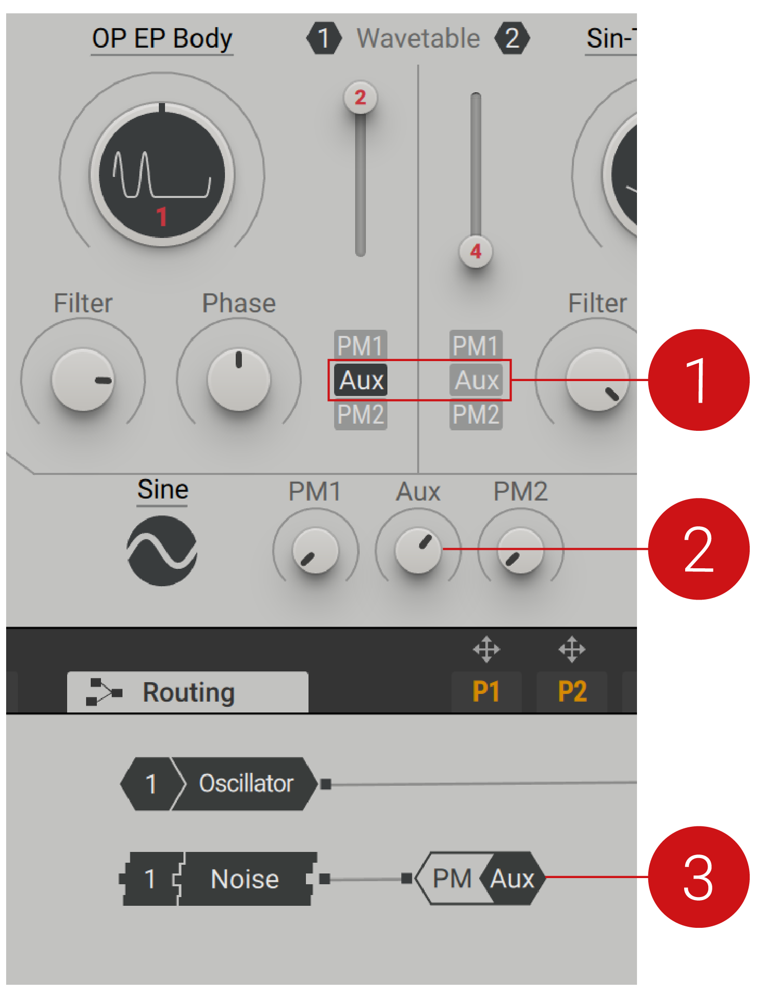 |
Aux Assignment: Assigns the signals received at the input of the PM Aux bus to the corresponding Wavetable oscillator.
Aux Modulation Amount: Adjusts the amount of phase modulation applied from the PM Aux bus to the Wavetable oscillators.
PM Aux Bus: This bus features a single input that sends signals to the phase modulation function of the Wavetable oscillators. It can be connected to the generators and processors in the Polyphonic Area.
Feedback loop
The feedback loop in the Polyphonic Area of the Routing page facilitates a connection from an output of a module to its input. Any number of modules can be chained in the feedback loop. This way you can add chaotic and non-linear behavior to the voice, which creates organic and distorted sounds. You can use feedback to enhance the sound or as a dramatic effect, with high feedback levels causing sonic mayhem. The feedback loop is also useful for physical modeling sounds, especially when combined with the Comb filter.
The feedback loop can be freely connected in the Polyphonic Area of the Routing page by using the two FB modules:
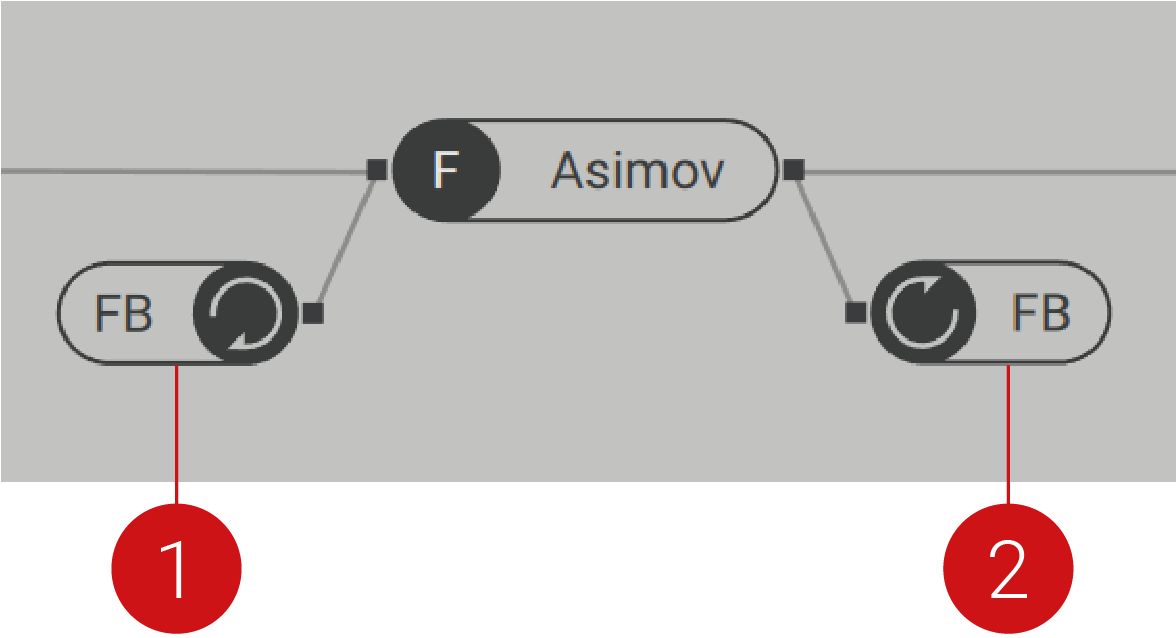 |
FB (feedback) Loop Output: This bus features a single output that receives signals from the feedback loop input. It can be connected to the generators, processors, and buses in the Polyphonic Area.
FB (feedback) Loop Input: This bus features a single input that sends signals to the feedback loop output. It can be connected to the generators and processors in the Polyphonic Area.
In the example above, the output of the Asimov filter is connected to the FB input, and the FB output is connected to the input of the Asimov filter. This creates a feedback loop around the filter, making it sound distorted and behave in unexpected yet interesting ways.
Tip
Note that the feedback loop is polyphonic, meaning it is processed independently for every single voice you play. This way you can play chords and overlapping notes with your feedback sounds.
Feedback Level Control
The feedback amount is controlled from the Amp module. Use the FB control to adjust the feedback level and apply a high-pass filter to reduce bass overloading in the feedback loop.
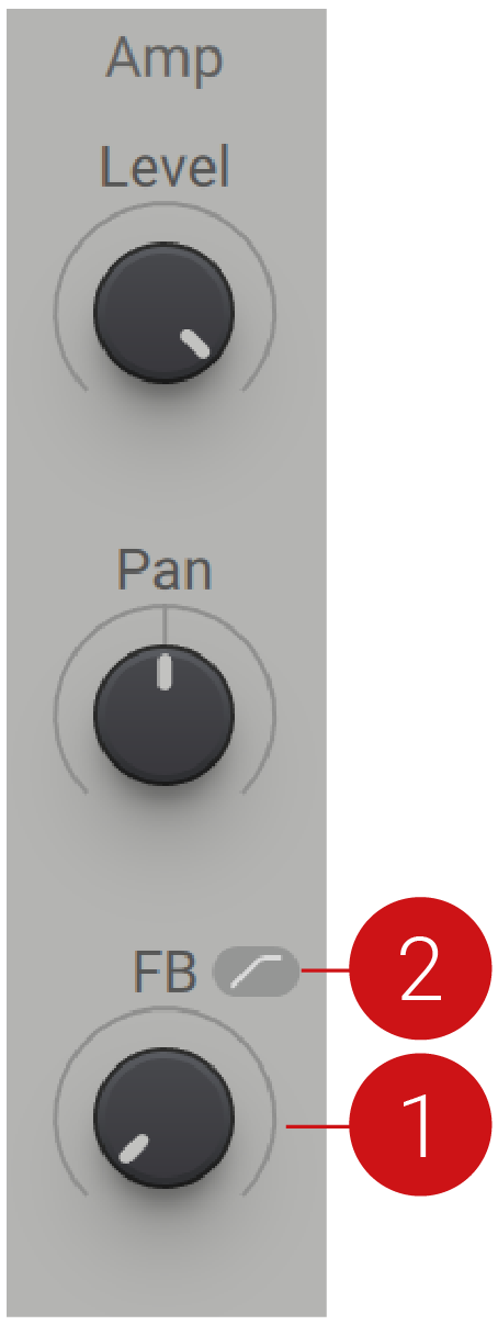 |
FB (feedback) Level: Adjusts the level, or volume of the feedback loop. This way you can control the chaotic behavior and distortion produced by the feedback.
High-pass Filter: Enables a high-pass filter that cuts low-frequency content in the feedback loop. When activated, you can avoid overloading the feedback loop with excessive bass.
Modulation modules
The Modulation modules in the Polyphonic Area of the Routing page make it possible to use any of Massive X's modulation sources as generators in the signal path. For example, you can use the Switcher LFO in OSC mode as an additional oscillator, or the Exciter Envelope as an exciter for the Comb filter.
To assign a modulation source to a Modulation module in the Polyphonic Area:
Click the modulation source's arrow icon to select it.
Click on the Modulation module slot in the Polyphonic Area to assign it.
The signal produced by the modulation slot is now sent from the Modulation module's output and can be used anywhere in the signal path.
Using the Routing page
On the Routing page, you arrange and connect the individual building blocks, or modules, that make up the synthesizer. Connections between the modules' inputs and outputs are established using wires. Outputs can be connected to any number of inputs and vice versa. This way you can distribute signals to multiple destinations or mix multiple outputs into the same input:
Routing Workflows
To make a connection between modules:
Click on an output to show all available inputs it can be connected to.
Click on the input you want to connect the output to.
Note
Alternatively, you can click and drag from an output to an input to connect them.
To make an exclusive connection to an input, meaning that all existing connections to the input will be removed:
Click on an output to show all available inputs it can be connected to.
Right-click on the input you want to connect the output to exclusively.
To delete a wire:
Double-click the wire you want to remove.
The wire is deleted.
To delete all connections from a module:
Double-click the module that you want to remove all connections from.
All connections are deleted.
You can also bypass any number of modules directly on the Routing page. This provides a quick way of listening to the sonic impact that a generator or processor is having on the sound.
To bypass a module while keeping its connections intact:
Right-click the module you want to bypass.
The module icon is dimmed and the module is deactivated.