Modulators
Modulation is a key component of all forms of synthesis. Massive X provides nine modulation sources that can be assigned to almost any parameter.
Modulation is a key component of all forms of synthesis. It is the way in which you shape a signal and the tool with which to breath life and movement into a sound. Massive X provides nine modulation sources in the form of Modulators, which can be used to control various parameters across the synth. Modulator 1 is a dedicated Amp-Envelope, hard-wired to control the Amplifier level. Each of the remaining eight Modulators can be assigned to any of the four modulation sources: Modulation Envelope, Exciter Envelope, Switcher LFO, and Random LFO. On a basic level, Modulators can be used to apply LFOs or envelopes to create simple contours or add motion to a sound. However, through an extensive network of modulation routing possibilities, as well as the specific controls of the Modulators themselves, more intricate arrangements can be constructed.
The Modulators are accessed and assigned via the Navigation Bar using the tabs labeled e.g. E1, E2, E3 for envelopes and L1, L2, L3 for LFOs. For information on how to assign the Modulators to parameters, refer to Assigning modulation.
The flexible and comprehensive range of modulation sources and routing possibilities provide considerable power for sound design. When properly exploited, the Modulators can go beyond your basic modulation needs, facilitating more advanced applications, like physical modeling, velocity-sensitive envelope shaping, multi-stage envelopes for complex shaping and so much more.
Envelopes
Envelopes are one of the most common and powerful tools for contouring your synth sound. In more typical use cases, envelopes control the loudness of an amplifier, shape the tone and color of a filter, or adjust the pitch of a signal. They can also be used for more creative objectives, like applying modulation to the speed of a sequence, the delay time of a stereo effect, or the rate of another Modulator.
LFOs
While envelopes create motion by defining the contour over a set of time and level based stages, LFOs typically have a fixed wave shape, useful for producing cyclical, predictable rhythmic modulation. LFOs (low frequency oscillators) produce a signal below the human range of hearing. As the signal cannot be heard, it is ideal for producing movement and animation, adding a sense of motion and depth to a sound. Modulation effects can become a defining character of a sound, for example, vibrato when an LFO is applied to the pitch of an oscillator, or tremolo when applied to an amplifier. Slow LFOs allow for subtle, elongate changes over time, while higher frequency rates can be used as a source for frequency modulation, amplitude modulation, and other types of audio-rate modulation.
Modulators overview
The Modulators feature the following key elements and controls:
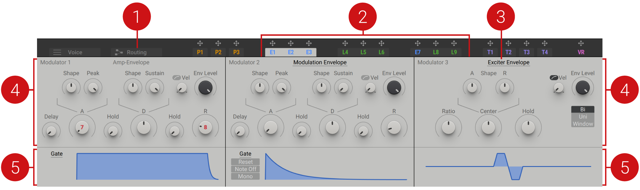
Routing tab: Two Modulation modules can be accessed via the Routing page, allowing you to use modulation sources as generators in the signal path. For more information, refer to Modulation modules.
Modulators: The Modulator type and number of the assigned to each slot is displayed here. Envelopes are represented with a blue E and LFOs are represented with a green L. Click on a Modulator to display the corresponding parameters. When a Modulator is selected, its tab is highlighted as in the image above. Click on the arrow icon above the Modulator to assign it to a modulation slot. For more information, refer to Assigning modulation.
Modulator menu: Select from four modulation sources (Modulation Envelope, Exciter Envelope, Switcher LFO, Random LFO).
Controls: The knobs and menus in this section are used to edit the shape and behavior of the Modulators.
Display: A visual representation of the current shape of the Envelope is displayed here, as determined by the trigger and knob settings. Moving the controls will show how each parameter influences the shape of the Envelope. Additional menus and settings relating to the behavior of the Modulator are also found here.
Amp Envelope
The Amp Envelope is used to control the response and shape of the Amplifier. Hardwired to the Amplifier, it offers individual scaleable curve controls over the Attack and Release stages, as well as Delay and Hold stages that provide additional control over the Amplifier's articulation.
In relation to human perception of amplification, small changes at low amplitude typically have a distinct and pronounced effect, while small changes made at higher volumes produce a less obvious result. Exponential shapes, as found on the Shape controls are especially effective for controlling the amplitude as they work to balance out the logarithmic shape of the amplifier, producing a smoother and more continuous change in volume.
The Trigger modes allow you to adapt to the way the Amplifier receives MIDI triggers. Gate mode is particularly useful when playing with a keyboard, as it provides a way to control the sound depending on the duration and intensity at which a key is pressed and held. For more information about the Amplifier, refer to Amplifier.
The Amp Envelope contains the following parameters and controls:
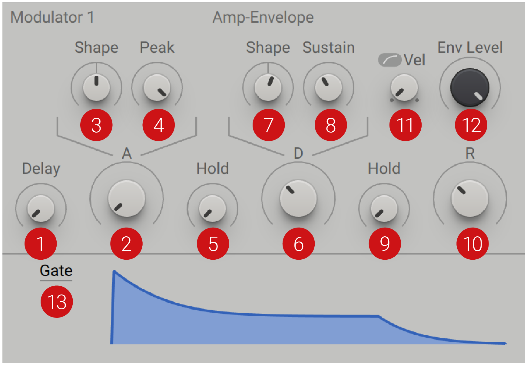 |
Delay: Applies a delay to the onset of the envelope. When turned fully left, no delay time is applied and the envelope starts at the Attack stage. Turning the knob right increases the delay time.
Attack (A): Adjusts the time the envelope takes to reach the peak level. Turned fully left, the envelope will start immediately. As you turn the control right, the Attack becomes longer, and your sound will have a smoother start.
Attack Shape: Changes the curve of the Attack stage of the envelope. Turning the knob left to right fades the curve from exponential to linear to logarithmic.
Attack Peak: Defines the maximum level that can be reached. The scope of this control is dependant on the Velocity setting.
Hold: Determines the fixed amount of time that the peak level of the envelope is held between the end of the Attack stage and the start of the Decay stage.
Decay (D): Adjusts the amount of time it takes to fall from the attack's maximum Peak level to the level defined by the Sustain control. Turned fully left, the Decay stage will start immediately, and turning the knob right increases the Decay time.
Decay Shape: Changes the curve of the Decay stage of the envelope. Turning the knob left to right fades the curve from exponential to linear, and then to logarithmic.
Decay Sustain: Sets the amplitude of the Sustain stage.
Hold: Determines the fixed amount of time that the peak level of the envelope is held between the end of the Sustain stage and the start of the Release stage.
Release (R): Defines the amount of time it will take for the envelope to fall from the set Sustain level and fade to zero.
Env Level: Defines the overall level of the envelope.
Velocity: Controls the influence of the incoming MIDI note’s velocity on the overall amplitude of the envelope. When turned fully left, the envelope amplitude is not influenced by the velocity of the incoming notes. When the fader is turned fully right, the overall envelope amplitude is directly proportional to the velocity of the incoming notes. The Velocity button changes the slope of the Velocity control from linear to logarithmic, when activated.
Trigger: Selects one of three settings (Gate, OneShot, LoopGate), that determine the envelope's response to incoming MIDI notes.
With Gate is selected, the envelope is started and read out until its end when triggered. If the key is released before the Sustain stage of the envelope, it will immediately jump to the Release stage.
With OneShot selected, the envelope is read to end, even if the key is released before the Sustain stage.
LoopGate creates a loop between the Attack and Decay stages.
Loop creates a loop from the entirety of the envelope, including the Release stage.
Display: Provides a visual representation of the envelope shape, based on how the knobs and menus are set. Move the controls described above to see how each parameter influences the shape of the envelope.
Modulation Envelope
The Modulation envelope in Massive X offers a highly flexible and precise way of shaping your signal. Through comprehensive routing options, this envelope can be used to control virtually any aspect of the signal.
Alongside the standard Attack, Decay, Sustain and Release parameters, one Delay stage and two Hold stages provide additional control over the shape and contour of the envelope, enabling you to create sounds that seemingly have multiple sustain stages. The Delay control is typically used to delay the start of modulation, or to delay the impact of a modulation source. It occurs before the start of the envelope and can be particularly useful in sound design, for example, creating a measured time between the onset of the Amplifier envelope and a Filter envelope. By delaying the Filter envelope, a double attack-style effect is produced, opening a world of intricate sound design possibilities.
Attack Shape and Decay Shape allow you to determine the slope of the envelope when rising and falling. This allows for more precise sculpting and contouring, as different shapes are more suitable for different musical uses. Linear shapes set a direct path from one stage to the next, while exponential curves are commonly used to create pitch sweeps, as they create a more effective continuous sweep than a linear or logarithmic envelope.
The Modulation Envelope contains the following parameters and controls:
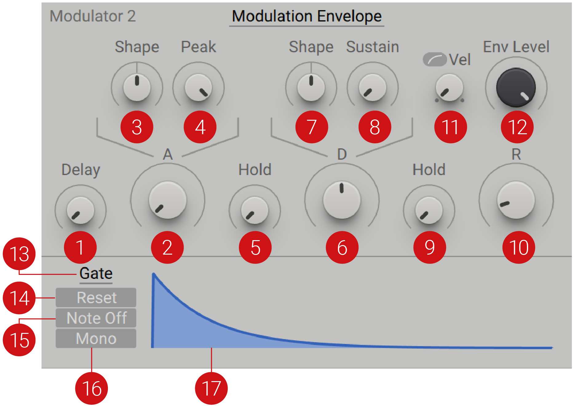 |
Delay: Applies a delay to the onset of the envelope. When turned fully left, no delay time is applied and the envelope starts at the Attack stage. Turning the knob right increases the delay time.
Attack (A): Adjusts the time the envelope takes to reach the peak level. Turned fully left, the envelope will start immediately. As you turn the control right, the Attack becomes longer, and your sound will have a smoother start.
Attack Shape: Changes the curve of the Attack stage of the envelope. Turning the knob left to right fades the curve from exponential to linear, and then to logarithmic.
Attack Peak: Defines the maximum level that can be reached. The scope of this control is dependant on the Velocity setting.
Hold: Determines the fixed amount of time that the peak level of the envelope is held between the end of the Attack stage and the start of the Decay stage.
Decay (D): Adjusts the amount of time it takes to fall from the attack's maximum Peak level to the level defined by the Sustain control. Turned fully left, the Decay stage will start immediately, and turning the knob right increases the Decay time.
Decay Shape: Changes the curve of the Decay stage of the envelope. Turning the knob left to right fades the curve from exponential to linear to logarithmic.
Decay Sustain: Sets the amplitude of the Sustain stage.
Hold: Determines the fixed amount of time that the peak level of the envelope is held between the end of the Sustain stage and the start of the Release stage.
Release (R): Defines the amount of time it will take for the envelope to fall from the set Sustain level and fade to zero.
Env Level: Defines the overall level of the envelope.
Velocity: Controls the influence of the incoming MIDI note’s velocity on the overall amplitude of the envelope. When turned fully left, the envelope amplitude is not influenced by the incoming note’s velocity. When the fader is turned fully right, the overall envelope amplitude is directly proportional to the incoming note’s velocity. The Velocity button changes the slope of the Velocity control from linear to logarithmic, when activated.
Trigger: Selects one of four settings (Gate, OneShot, LoopGate, Loop), that determine the envelope's response to incoming MIDI notes.
When Gate is selected, the envelope starts and is read out until its end. If the key is released before the Sustain stage of the envelope, it will immediately jump to the Release stage.
With OneShot selected, the envelope is read to end, even if the key is released before the Sustain stage.
LoopGate creates a loop between the Attack and Decay stages.
Loop creates a loop from the entirety of the envelope, including the Release stage.
Reset: When active, the envelope will restart each time a note is triggered.
Note Off: When active, the envelope is triggered with the note-off stage, for example when a key is released.
Mono: When activated, all incoming notes receive the same envelope shape, regardless of pitch.
Display: Provides a visual representation of the envelope shape, based on how the knobs and menus are set. Move the controls described above to see how each parameter influences the shape of the envelope.
Exciter Envelope
The Exciter envelope is a particularly fast envelope that has been specifically designed to trigger the Comb filter, producing a resonator in physical modelling. It also effective for creating percussive sounds, with its quick attack and short release times.
The Exciter is unlike a standard ADSR based, multi-stage envelope generator. It is an Attack-Release envelope with short times, functioning in a single cycle, with a defined centre point and Hold stage that maintains the peak level from Attack to Release stages.
To use this envelope as an exciter for the Comb filter, it must be assigned to one of the Modulation Sources via the Routing page, routed to the Comb filter and then the filter routed to the output. This enables you to set the Comb filter into oscillation and create tones from the Feedback. A low Ratio setting produces the short envelope burst needed to create sound from the filter. For more information, refer to Comb.
Tip
You can also use the Exciter envelope to briefly trigger self-oscillation of resonant filters at high Res settings. This so-called filter pinging produces a damped sine wave that can be played via MIDI by using key tracking (KTR). The SVF filter types are especially suitable for this purpose.
The Exciter Envelope contains the following parameters and controls:
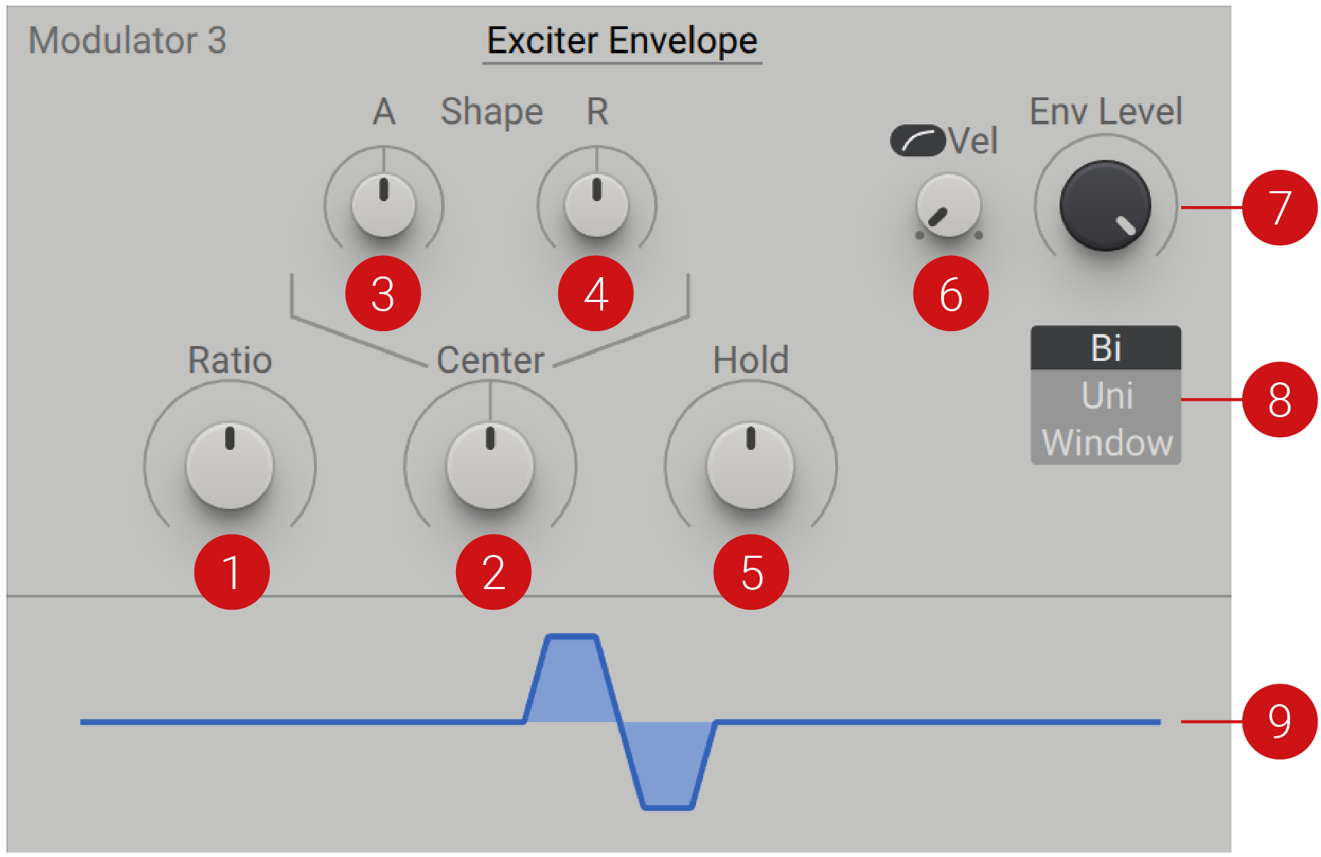 |
Ratio: Controls the length of the envelope. Turning the knob right, increases the value, resulting in a longer envelope.
Center: Tilts the envelope towards the Attack stage when turned left, or towards the Release stage when turned right.
Attack Shape: Changes the curve of the attack (A) stage of the envelope from parabolic to logarithmic.
Release Shape: Changes the curve of the release (R) stage of the envelope from parabolic to logarithmic.
Hold: Increases the width of the peak stage of the envelope, determining how long the level of this stage will be held.
Velocity: Controls the influence of the incoming MIDI note’s velocity on the overall amplitude of the envelope. When turned fully left, the envelope amplitude is not influenced by the velocity of the incoming notes. When the fader is turned fully right, the overall envelope amplitude is directly proportional to the velocity of the incoming notes. The Velocity button changes the slope of the Velocity control from linear to logarithmic, when activated.
Env Level: Defines the overall level of the envelope.
Polarity: Selects one of three settings (Bi, Uni. Window) that determine the direction of modulation.
When Bi is selected, the modulation is bidirectional.
With Uni selected, the modulation is unidirectional and moves only in one direction.
When Window is selected, the envelope is unidirectional and mirrored at the center. This removes the independent controls for attack and release, and offers only one shape control as the stages are now identical.
Display: Provides a visual representation of the envelope shape, based on how the knobs and menus are set. Move the controls described above to see how each parameter influences the shape of the envelope.
Switcher LFO
The Switcher LFO offers a suite of LFO types, optimized for different use cases. The LFO is made up of the Rate, Shape, and Amp sections, running from left to right. The Rate section determines the speed and the play mode of the LFO. Depending on the mode selected, the Rate knob will change its appearance and functionality. Osc mode, provides an extremely fast modulation option that can be used in sync with the pitch of the Wavetable oscillators. The Shape section offers 16 different waveform shapes, from the typical Sine, Triangle, Saw and Square, to Ramp, Random, Spike and more.
Assigning a modulation source to the Shape selector allows you to scan through the different LFO shapes, creating some dramatic sonic effects. The Fall/Rise control in the Amp section can be used to determine the fade in and fade out of the LFO. The envelope is not velocity sensitive, and always restarts each time a MIDI gate is received. This can be particularly useful in musical applications, for example, when using the LFO for pitch vibrato, it enables you to fade in the vibrato slowly. The flexible shapes allow you to customise your LFO to tailor very specific modulation tasks.
The Play modes determine whether the LFO loops continuously or plays through one cycle only, and how the LFO cycle resets in response to incoming MIDI triggers. In addition to standard Gate and Restart behavior, Loop REL mode can be used to create interesting release effects.
The Switcher LFO contains the following parameters and controls:
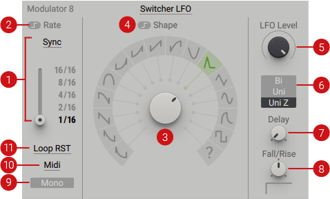 |
Rate Mode: Selects one of three modes (Sync, Free, OSC), which determine the rate in which the LFO repeats its cycles.
In Sync mode, the LFO is synchronized to the host tempo. It provides a slider with five positions, each of which can be programmed to your desired time division. Editing the numerator and denominator separately allows you to produce specific time divisions, and also facilitates more esoteric ones. Sync mode organizes the denominator values in a non-linear manner, to provide quick access to the most common values. Standard values /4, /8, /16, /32 are then followed by triplets /12 (8-note triplets), /24 (16-note triplets), /48 (32-note triplets), and so on, until 99. The change of Rate happens as soon as the slider hits a new position, with no fading in between.
In Free mode, the Rate is absolute and independent from the host tempo. The slider subdivision are replaced with a continuous knob to control the speed of the LFO. The range, in Hz, extends from very slow to very fast rates. The knob is scaled in this respect, giving finer control in the middle ranges. The overall rate range is 0.004 Hz to approximately 60 Hz. Centre position is around 5.3 Hz, which is ideal for pitch vibrato.
In Osc mode, the LFO operates at audio rate, becoming an additional keytracking oscillator. The values generated by the Rate control are linked to incoming MIDI notes, turning Rate into a control for transposition, ranging from zero when turned fully right, down to -96 semitones lower than the note pitch.
Latch Rate: When activated, changes to the Rate (via direct control or modulation) are latched until the next note is received.
Waveform Selector: Selects one of sixteen waveforms for the LFO. The new shape is updated with each cycle, providing a synchronized switch when heavily modulated.
Latch Shape: When activated, changes to the Shape (via direct control or modulation) are latched until the next note is received.
LFO Level: Amplifies the output of the LFO. Turning the knob right increases the amplification level.
Polarity: Selects from three Polarity settings (Bi, Uni, Uni Z) that determine how the envelope in the Amp section behaves.
When Bi (Bipolar) is selected, the output range of the LFO is -100% to +100%. The waveform always starts at 0%, independent of which shape is selected.
Uni (UniPolar) offers a range of 0 to 100%. The waveform will always start at 50%, independent of the selected shape.
Uni Z (UniPolar Zero) also has a range of 0 to 100% . The differences between Uni and Uni Z can only be heard when the oscillator is restarted with a new note trigger. The Polarity setting is reflected in the modulation.
Delay: Applies a delay to the onset of the LFO. When turned fully left, no delay time is applied and the LFO starts immediately. Turning the knob right increases the delay time.
Fall/Rise: Adjusts the way the LFO fades in or out. At centre position the LFO has infinite falling time, working as though it is always on. Turning the knob right produces a short rising ramp that becomes longer as it is turned fully right. Turning the knob left creates a very small decay fall time, which extends to a very long falling time as the control is turned fully left. The display, located below the Fall/Rise knob, provides a visual representation of the shape of the fades.
Mono: When deactivated, the LFO is polyphonic. Each incoming note receives its own LFO. When activated, the LFO is monophonic and all incoming notes receive the same LFO, regardless of pitch.
Midi: Switches between Midi and Remote mode for resetting and latching the LFOs. When Midi is selected the LFO resets and latches based on incoming MIDI note events. If Remote is selected the LFO resets and latches when you change key switches in the Remote Octave.
Play Mode: Selects from six settings (Loop, Loop RST, Loop GTE, Loop REL, 1shot, 1shot REL), that determine the general behavior of the LFO.
Loop is the most classic setting, with the LFO running in an infinite loop, regardless of whether notes are being played or not.
Loop RST (Loop Restart) also runs in an infinite loop, but will immediately jump to a given phase if a MIDI trigger is received from Zone or Remote.
Loop GTE (Loop Gate) follows the same behavior as Loop Restart, but cuts the LFO as soon as the note is released.
Loop REL (Loop Release) deactivates the LFO as soon as note is received. When the note is released, the LFO resets and the modulation is in effect. In this mode, it is important to set a long release time on the Amp envelope, or the effect will not be heard.
When 1shot (One Shot) is selected, only one cycle of the LFO will be played. Note on will always restart the LFO and go to zero after the cycle, regardless of the LFO value or polarity setting. This ensures predictable results, regardless of the LFO waveform.
1shot REL (One Shot Release) follows the same principles as 1shot mode, but creates a cycle when the note is released. In this mode it is also important to set a long Release time on the Amp envelope, or the effect will not be heard.
Tip
When in Sync mode, try modulating the Rate with another Switcher LFO. While sweeping through the positions on the slide, experiment in programming subtle variations in time divisions.
Random LFO
Adding randomness to your signal can inject human-like character to an otherwise highly controlled sound. This naturalistic quality is grounded in chance, probability and human error; the essence of what distinguishes a drummer from a drum machine. The Random LFO is a specialized LFO that generates different kinds of controllable variable random numbers, and provides controls to alter the type, range and amount of randomness applied.
The Random LFO can also be used as a generator by activating the Audio Noise button. Assigning the LFO to a Modulation source via the Routing page enables you to use the LFO as a noise source in the audio signal path. For more information on using Modulators as generators, refer to Modulation modules.
The Amp Jitter can be used to produce a precise amount of random values. Mixing between the two extremes, particularly with fast Rate settings, has a significant impact on the color of the noise. The independent controls can produce a wide range of noises and random modulations.
The Random LFO contains the following parameters and controls:
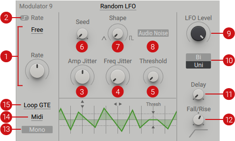 |
Rate mode: Selects one of three modes (Sync, Free, OSC), which determine the rate in which the LFO repeats its cycles.
In Sync mode, the LFO is synchronized to the host tempo. A slider offers five positions, each of which can be programmed to your desired time division. Editing the numerator and denominator separately allows you to produce specific time divisions, and also facilitates more esoteric ones. Sync mode organizes the denominator values in a non-linear manner, to provide quick access to the most common values. Standard values /4, /8, /16, /32 are then followed by triplets /12 (8-note triplets), /24 (16-note triplets), /48 (32-note triplets), and so on, until 99. The change of Rate happens as soon as the slider hits a new position, with no fading in between.
In Free mode, the Rate is absolute and independent from the host tempo. The slider subdivision are replaced with a continuous knob to control the speed of the LFO. The range, in Hz, extends from very slow to very fast rates. The knob is scaled in this respect, giving finer control in the middle ranges. The overall rate range is 0.004 Hz to approximately 60 Hz. Centre position is around 5.3 Hz, which is ideal for pitch vibrato.
In Osc mode, the LFO operates at audio rate, becoming an additional keytracking oscillator. The values generated by the Rate control are linked to incoming MIDI notes, turning Rate into a control for transposition, ranging from zero when turned fully right, down to -96 semitones lower than the note pitch.
Latch Rate: When activated, changes to the Rate (via direct control or modulation) are latched until the next note is received.
Amp Jitter: Adjusts the amount of random modulation applied to the amplitude of the signal. Turned fully left, the basic waveform of the LFO is unaltered. Turning the knob right increases the amount of unpredictable values. When turned fully right, a completely random value is produced with each cycle.
Freq Jitter: Adjusts the amount of random modulation applied to the frequency of the signal. Turned fully left, the basic waveform of the LFO is unaltered. Turning the knob right increases the random frequency fluctuation. This can produce results similar to white noise, if Amp Jitter is set to a low value. Freq Jitter is only available in Free and Osc modes.
Threshold: Provides further treatment for the amplitude, and only has an effect if the Amp Jitter is turned up. Random values below a set Threshold are forced to zero, which can be used to drastically thin out the noise.
Seed: Adjusts the seed that feeds the random sequence introduced by Amp Jitter and Freq Jitter. This control is only available in the play modes Loop RST, Loop GTE, and Loop REL. Adjusting Seed produces a new random sequence, starting with the next reset event. You can use this to explore different randomly acquired waveforms and repeat them with every new note.
Shape: Adjusts the shape and smoothness of the ties between values. Technically speaking, it's applying a linear interpolation to the values. When turned fully left, a smooth interpolation is produced and when turned right, hard steps are created.
Audio Noises: When activated, the LFO operates in audio rate. This turns the LFO into a Noise generator, which when assigned to a modulation source in the Routing page, can be used in the audio signal path.
LFO Level: Amplifies the output of the LFO. Turning the knob right increases the amplification level.
Polarity: Selects from two Polarity settings (Bi, Uni) that determine how the envelope in the Amp section behaves. When Bi (Bipolar) is selected, the output range of the LFO is -100% to +100%. The waveform always starts at 0%, independent of which shape is selected. Uni (UniPolar) offers a range of 0 to 100%. The waveform will always start at 50%, independent of the selected shape.
Delay: Applies a delay to the onset of the LFO. When turned fully left, no delay time is applied and the LFO starts immediately. Turning the knob right increases the delay time.
Fall/Rise: Adjusts the way the LFO fades in or out. At center position the LFO has infinite falling time, working as though it is always on. Turning the knob right produces a short rising ramp that becomes longer as it is turned fully right. Turning the knob left creates a very small decay fall time, which extends to a very long falling time as the control is turned fully left. The display, located below the Fall/Rise knob, provides a visual representation of the shape of the fades.
Mono: When deactivated, the LFO is polyphonic. Each incoming note receives its own LFO. When activated, the LFO is monophonic and all incoming notes receive the same LFO, regardless of pitch.
Midi: Switches between Midi and Remote mode for resetting and latching the LFOs. When Midi is selected the LFO resets and latches based on incoming MIDI note events. If Remote is selected the LFO resets and latches when you change key switches in the Remote Octave.
Play mode: Selects from six settings (Loop, Loop RST, Loop GTE, Loop REL, 1shot, 1shot REL), that determine the general behavior of the LFO.
Loop is the most classic setting, with the LFO running in an infinite loop, regardless of whether notes are being played or not. When turning Amp Jitter and Freq Jitter to the right, the waveform will randomly change over time.
Loop RST (Loop Restart) also runs in an infinite loop, but will immediately jump to a given phase if a MIDI trigger is received from Zone or Remote. When turning Amp Jitter and Freq Jitter to the right, the waveform will change randomly over time, but start the same random sequence again upon receiving a MIDI trigger.
Loop GTE (Loop Gate) follows the same behavior as Loop Restart, but cuts the LFO as soon as the note is released. When turning Amp Jitter and Freq Jitter to the right, the waveform will change randomly over time, but start the same random sequence again when the note is released.
Loop REL (Loop Release) deactivates the LFO as soon as note is received. When the note is released, the LFO resets and the modulation is in effect. In this mode, it is important to set a long release time on the Amp envelope, or the effect will not be heard. When turning Amp Jitter and Freq Jitter to the right, the waveform will change randomly over time, but start the same random sequence again when the note is released.
When 1shot (One Shot) is selected, only one cycle of the LFO will be played. Note on will always restart the LFO and go to zero after the cycle, regardless of the LFO value or polarity setting. This ensures predictable results, regardless of the LFO waveform.
1shot REL (One Shot Release) follows the same principles as 1shot mode, but creates a cycle when the note is released. In this mode it is also important to set a long Release time on the Amp envelope, or the effect will not be heard.
Tip
To get started, try applying the Random LFO to the Pitch of an oscillator, or the Wavetable Position. Turn the Shape control toward the square shape to create rhythmic variations in pitch and timbre. Experiment with all the settings to hear the range of noises and random voltages you can create.