Filter
This chapter covers Massive X's Filter section, including all available filter types, their respective controls, and suggestions for most effective use.
The Filter is a key element in Massive X's voice architecture. It offers nine different types of filters that cover a wide range of different applications. It can be used to balance and correct the tone of a sound, to sculpt complex timbres from raw waveforms, and to transform sounds beyond recognition.
Additionally, a number of filter types can be set into oscillation and become sound generators on their own. In some instances, this can be achieved by increasing the resonance for self-oscillation, in other instances the filter can be excited using the special Exciter envelope or noise signals for physical modeling sounds. Selecting where to place the Filter in the signal chain is done via the Routing page. For more information, see Generators and processors.
The Filter section contains the following key elements:
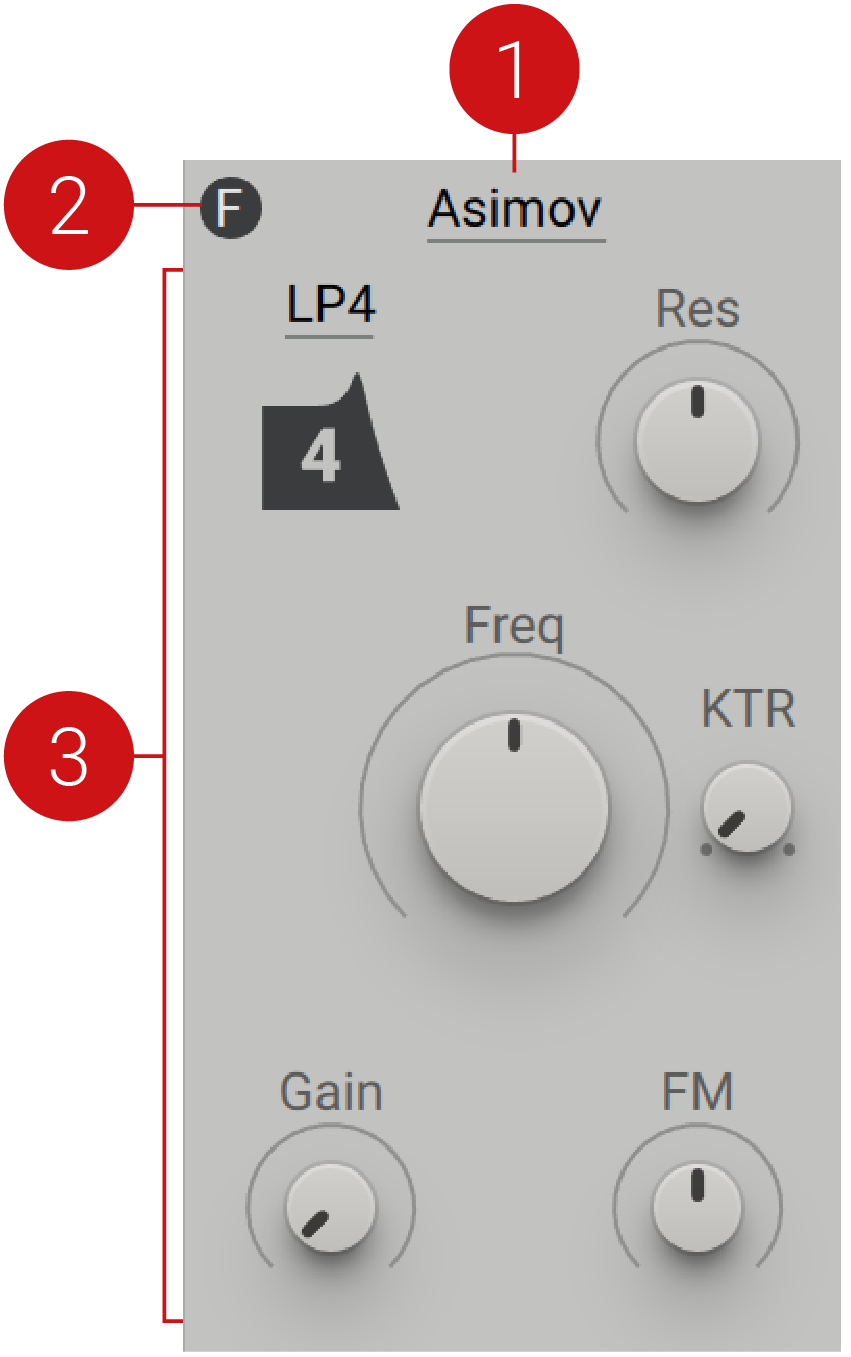 |
Bypass switch: Switches the Filter's bypass function on or off. The icon can also be found on the Filter module on the Routing page.
Filter menu: Selects the filter type.
Parameter controls: This area hosts a range of buttons and knobs that control different parameters of the selected filter type. Each filter type has a different selection of controls that relate to its behavior and operation.
Asimov
This low-pass filter is based on the paradigm of the filter found in a classic bass synthesizer from the 80s, despite not being a direct clone. Its defining characteristic is the lack of self-oscillation, providing a huge sweet-spot for resonant filter sounds. Additionally, it adds high-pass filtering in the feedback path for a controlled bass response. The filter has a squelchy sound that makes it suitable for acid bass lines and works well with distortion.
Asimov contains the following parameters and controls:
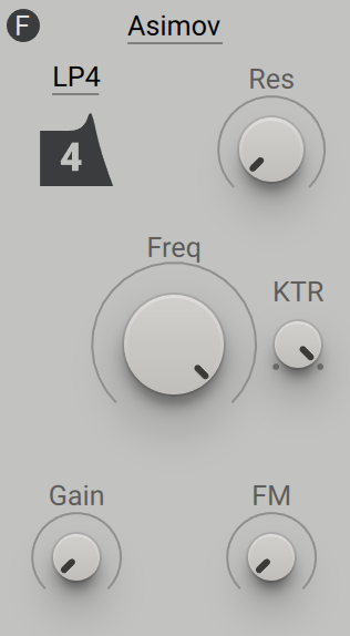 |
Filter mode: Selects one of three modes (LP1, LP2, LP4) that determine the steepness of the low-pass filter. LP1 (low-pass 1-pole) has a slope of 6 dB/Oct, LP2 (low-pass 2-pole) has a slope of 12 dB/Oct, and LP4 (low-pass 4-pole) has a slope of 24 dB/Oct.
Res: Adjusts the resonance amount of the low-pass filter. Turning Res to the right increases the resonance, causing the frequency content at the cutoff frequency to become more pronounced.
Freq: Adjusts the cutoff frequency of the low-pass filter. Frequency content above the cutoff frequency is attenuated, creating a darker sound.
KTR: Adjusts the amount of key tracking, which is the degree to which the filter's cutoff frequency follows the MIDI pitch.
Gain: Adjusts the input level and increases the amount of saturation applied to the signal.
FM: Adjusts the amount of audio rate modulation applied to the filter frequency, also called filter FM (frequency modulation). The FM source needs to be connected to the FM bus on the Routing page, otherwise the FM control will not have an effect.
Blue Monark
This multi-mode filter is a polyphonic adaptation of the filter found in NI's Monark, with additional modes and slightly different non-linear behavior. Its defining characteristic is the ability to drive the filter into saturation using the Gain control. Additionally, it offers audio-rate modulation of the filter frequency and is capable of self-oscillation. Feedback can be patched in a flexible manner on the Routing page. The filter has a warm and fat character that makes it suitable for overdriven bass sounds as well as classic leads.
Blue Monark contains the following parameters and controls:
 |
Filter mode: Selects one of seven modes (LP1, LP2, LP4, BP, Peak, HP, Dual Notch) that determine the response and steepness of the filter. Three low-pass modes are available, each attenuating frequency content above the cutoff frequency with the given slope. LP1 (low-pass 1-pole) has a slope of 6 dB/Oct, LP2 (low-pass 2-pole) has a slope of 12 dB/Oct, and LP4 (low-pass 4-pole) has a slope of 24 dB/Oct. BP (band-pass) mode attenuates frequency content above and below the cutoff frequency. Peak mode adds a resonant filter peak at the cutoff frequency. HP (high-pass) mode attenuates frequency content below the cutoff frequency. Dual Notch mode attenuates frequencies in two narrow frequency bands (or notches) around the cutoff frequency.
Freq: Adjusts the cutoff frequency of the filter. The effect of this control on the sound depends on the selected filter mode. For more information, refer to Filter mode above.
Res: Adjusts the resonance amount of the low-pass filter. Turning Res to the right increases the resonance, causing the frequency content at the cutoff frequency to become more pronounced.
KTR: Adjusts the amount of key tracking, which is the degree to which the filter's cutoff frequency follows the MIDI pitch.
Gain: Adjusts the input level and increases the amount of saturation applied to the signal.
FM: Adjusts the amount of audio rate modulation applied to the filter frequency, also called filter FM (frequency modulation). The FM source needs to be connected to the FM bus on the Routing page, otherwise the FM control will not have an effect.
Comb
The Comb filter works differently from an analog filter; it delays the input signal and feeds it back onto itself, similar to an echo effect. However, the Comb is optimized for very short delay times, causing interferences in the audible range. This creates regularly spaced peaks and troughs in the frequency response, resembling the appearance of a comb. The effect gets more pronounced as feedback is increased. The Comb can be used as a tuned resonator in physical modeling, a complex filter for oscillator signals, or to create flanging effects. Instead of a typical filter frequency control with adjustable key tracking, it features the same Pitch control as found on the oscillators. This way, the incoming MIDI pitch is perfectly tracked, which facilitates its applications as a tuned resonator and complex harmonic filter.
Comb contains the following parameters and controls:
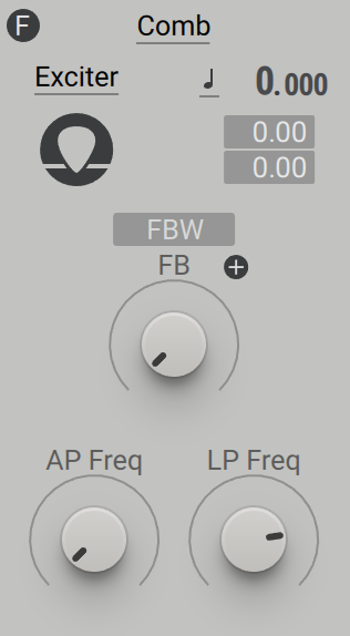 |
Filter mode: Selects one of three modes (Exciter, OSC, Flanger) that cater to different applications. Exciter is suitable for using Comb as a resonator in physical modeling (for example Karplus-Strong synthesis). This is done by setting the Comb filter into oscillation with a suitable signal, for example from the Exciter envelope via the Routing page's Modulation Sources, or the Noise source controlled by an envelope. OSC is suitable for using the Comb filter with periodic signals produced by an oscillator to create complex harmonic filtering effects. This mode compensates for resonance boosts caused by the harmonic frequencies of the oscillator signal. Flanger is suitable when using Comb as a flanging effect with a wide range of different signals.
Pitch Mode: Selects one of three modes (Keytrack, Fix, Ratio) that determine the response of the Comb in relation to incoming MIDI pitch. In Keytrack mode, the pitch is locked to the main MIDI pitch. Ratio mode multiplies or divides the MIDI pitch in relation to the ratio setting. For example, a ratio of 3 adjusts the pitch to 3 times the frequency, producing the 3rd harmonic. Fix mode sets the fixed tuning of the Comb, disregarding the incoming MIDI pitch. This mode displays MIDI note numbers, with the default set to 60 (middle C).
Pitch: Adjusts the tuning of the Comb in semitones and cents. The Pitch can be modulated to produce vibrato and arpeggio effects by routing a modulation source to either of the two modulation slots below. In technical terms, the tuning adjusts the size of the delay buffer inside of the Comb. A larger delay buffer causes a longer delay time, which results in a lower filter frequency. A smaller delay buffer causes a shorter delay time, which results in a higher filter frequency.
FBW: Switches between two different pickup points for the output in the signal flow. When off, the output is picked up after the delay. When activated, the output is picked up before the delay. This setting only takes effect in combination with specific configurations on the Routing page, for example when using the FB modules for external feedback around the Comb filter or when mixing the Comb filter's output signal with the input signal as part of a parallel routing.
Feedback Polarity: Switches between positive and negative polarity for the feedback signal. With positive feedback polarity the Comb filter produces all harmonics, while with negative feedback polarity it produces only odd harmonics.
FB: Sets the level of the internal feedback loop of the Comb. Higher settings increase the feedback level, resulting in a stronger resonance of the filter.
AP Freq: Adjusts the frequency of an all-pass filter in the Comb's feedback path. By changing the all-pass filter frequency, you can use the Comb to produce inharmonic spectra.
LP Freq: Controls the cutoff frequency of a low-pass filter in the feedback path. Decreasing the low-pass filter frequency attenuates the high-frequency content of the feedback signal, resulting in a dampened sound.
Creak
Creak is an experimental filter that stems from research into flangers. It produces strong resonances in the frequency spectrum and is characterized by its distinct non-linear behavior. Combined with the feedback loop on the Routing page, you can apply heavy distortion and spectral transformation to a sound. The filter has an aggressive and wild character that makes it suitable for radical sound design.
Creak contains the following parameters and controls:
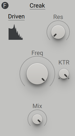 |
Filter mode: Selects one of four unique modes (Driven, Gnarl, Nosy, Euer). Driven and Gnarl produce different sets of harmonically spaced resonances similar to a flanger, Nosy produces formants with a nasal quality, and Euer produces formants with a vocal quality.
Freq: Adjusts the frequency of the filter. Unlike a typical cutoff control, it shifts the resonances across the frequency spectrum without attenuating broad frequency bands.
Res: Adjusts the intensity of the resonances in the frequency spectrum produced by the filter.
KTR: Adjusts the amount of key tracking, which is the degree to which the filter's frequency follows the MIDI pitch.
Mix: Blends between the input signal and the filtered signal.
Groian
Groian is a hybrid between a filter and a flanger. It features a delay with feedback in the filter's resonance path. This structure produces strong resonances in the frequency spectrum that are superimposed with the basic response of the filter. Combined with the feedback loop on the Routing page you can apply heavy distortion and spectral transformation to a sound. Self-oscillation is possible, however it becomes unstable towards lower frequencies. The filter has a highly resonant character that makes it suitable for creating vocal or even metallic sounds.
Groian contains the following parameters and controls:
 |
Filter mode: Selects one of four modes (LP4, BP, Peak, HP) that determine the response of the filter. LP4 (low-pass 4-pole) mode attenuates frequency content above the cutoff frequency with a slope of 24 dB/Oct. BP (band-pass) mode attenuates frequency content above and below the cutoff frequency. Peak mode adds a resonant filter peak at the cutoff frequency. HP (high-pass) mode attenuates frequency content below the cutoff frequency.
Freq: Adjusts the cutoff frequency of the filter. The effect of this control on the sound depends on the selected filter mode. For more information, refer to Filter mode above.
Res: Adjusts the resonance amount of the low-pass filter. Turning Res to the right increases the resonance, causing the frequency content at the cutoff frequency to become more pronounced.
KTR: Adjusts the amount of key tracking, which is the degree to which the filter's frequency follows the MIDI pitch.
Character: Adjusts the intensity of the additional resonances in the frequency spectrum produced by the delay in the resonance path.
FM: Adjusts the amount of audio rate modulation applied to the filter frequency, also called filter FM (frequency modulation). The FM source needs to be connected to the FM bus on the Routing page, otherwise the FM control will not have an effect.
Tip
The behavior of the filter is sensitive to the level of the input signal with stronger self-oscillation at lower input levels.
Scanner
This multi-mode filter is inspired by the raw sound of a number of analog monophonic synthesizers from the 80s. Its defining characteristic is the pronounced resonance behavior, which you can use to carve out the harmonics of a signal when doing filter sweeps. Strong non-linear properties add harmonic distortion to the resonance. The filter has a dirty character that makes it suitable for adding texture and character to stacked pads and leads.
Scanner contains the following parameters and controls:
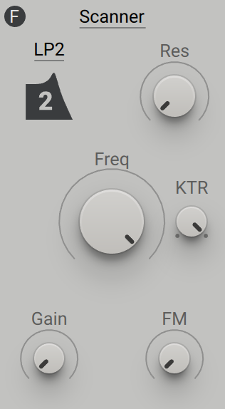 |
Filter mode: Selects one of four modes (LP1, LP2, BP2, Peak) that determine the response of the filter. Two low-pass modes are available, each attenuating frequency content above the cutoff frequency with the given slope: LP1 (low-pass 1-pole) with a slope of 6 db/Oct and LP2 (low-pass 2-pole) with a slope of 12 db/Oct. BP2 (band-pass 2-pole) attenuates frequency content above and below the cutoff frequency with a slope of 12 db/Oct. Peak mode adds a resonant filter peak at the cutoff frequency.
Freq: Adjusts the cutoff frequency of the filter. The effect of this control on the sound depends on the selected filter mode. For more information, refer to Filter mode above.
Res: Adjusts the resonance amount of the low-pass filter. Turning Res to the right increases the resonance, causing the frequency content at the cutoff frequency to become more pronounced.
KTR: Adjusts the amount of key tracking, which is the degree to which the filter's frequency follows the MIDI pitch.
Gain: Adjusts the input level and increases the amount of saturation applied to the signal.
FM: Adjusts the amount of audio rate modulation applied to the filter frequency, also called filter FM (frequency modulation). The FM source needs to be connected to the FM bus on the Routing page, otherwise the FM control will not have an effect.
Tip
The behavior of the filter is sensitive to the level of the input signal with stronger self-oscillation at lower input levels.
SVF
This multi-mode filter is based on the popular state-variable filter topology and serves as a tool for a wide range of filtering tasks. Its defining characteristic is the controlled behavior and universal applicability. The filter has a clean character that makes it suitable for any sound that requires tonal shaping without adding color or distortion.
SVF contains the following parameters and controls:
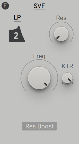 |
Filter mode: Selects one of five modes (LP2, LP4, BP, Peak, HP) that determine the response of the filter.
LP2 (2-pole low-pass) mode attenuates frequency content above the cutoff frequency with a slope of 12 dB/Oct.
LP4 (4-pole low-pass) mode attenuates frequency content above the cutoff frequency with a slope of 24 dB/Oct.
BP (band-pass) mode attenuates frequency content above and below the cutoff frequency with a slope of 6 db/Oct.
Peak mode (a band-pass filter mixed with the input signal) adds a resonant filter peak at the cutoff frequency.
HP (high-pass) mode attenuates frequency content below the cutoff frequency with a slope of 12 dB/Oct.
Freq: Adjusts the cutoff frequency of the filter. The effect of this control on the sound depends on the selected filter mode. For more information, refer to Filter mode above.
Res: Adjusts the resonance amount of the low-pass filter. Turning Res to the right increases the resonance, causing the frequency content at the cutoff frequency to become more pronounced.
KTR: Adjusts the amount of key tracking, which is the degree to which the filter's cutoff frequency follows the MIDI pitch.
Res Boost: Increases the range of the Res control to allow for a stronger resonance.
Tip
You can use the Exciter envelope via the Modulation sources on the Routing page to briefly trigger self-oscillation of the SVF at high Res settings. This so called filter pinging produces a damped sine wave that can be played via MIDI by using key tracking (KTR).
SVF Parallel
This dual multi-mode filter is based on the popular state-variable filter topology and serves as a tool for a wide range of filtering tasks. The two filters are arranged in a parallel configuration, meaning the input signal is sent to both of them separately, while the output signal is the sum of their individual outputs. Its defining characteristic is the controlled behavior and universal applicability. The filter has a clean character that makes it suitable for any sound that requires tonal shaping without adding color or distortion. Due to the parallel configuration of two filters, it is capable of producing vocal formants as well as complex wobble sounds.
SVF Parallel contains the following parameters and controls:
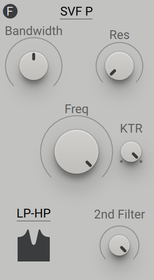 |
Filter mode: Selects one of seven modes that combine different responses of each of the two parallel filters. Six combinations of a 12 dB/Oct LP (low-pass) filter, a 12 dB/Oct HP (high-pass) filter, and a 6 dB/Oct (BP) (band-pass) filter are available, as well as the special Plateau mode.
Freq: Adjusts the cutoff frequencies of the two parallel filters. Both cutoff frequencies are offset by the same amount. Their relative position in the frequency position is set with the Bandwidth control.
Res: Adjusts the resonance amount of the low-pass filter. Turning Res to the right increases the resonance, causing the frequency content at the cutoff frequencies to become more pronounced.
Bandwidth: Spreads the cutoff frequencies of the two parallel filters in the frequency spectrum. At minimum setting, both filters share the same cutoff frequency, which makes the resonance much more pronounced. As Bandwidth is increased, the cutoff frequency of one filters moves down in frequency, while the other moves up. This way you can distribute the filter resonances to create formant frequencies.
KTR: Adjusts the amount of key tracking, which is the degree to which the filter's cutoff frequency follows the MIDI pitch.
2nd Filter: Blends between single and dual configurations of the filter by mixing in the second filter and adjusting the amount of frequency spread introduced by the Bandwidth control.
Tip
You can use the Exciter envelope via the Modulation sources on the Routing page to briefly trigger self-oscillation of the SVF Parallel at high Res settings. This so called filter pinging produces damped sine waves that can be played via MIDI by using key tracking (KTR).
SVF Serial
This dual multi-mode filter is based on the popular state-variable filter topology and serves as a tool for a wide range of filtering tasks. The two filters, a high-pass and a low-pass, are arranged in a serial configuration, meaning the input signal is sent to the high-pass filter, the output of which is going into the low-pass filter. Its defining characteristic is the controlled behavior and universal applicability. The filter has a clean character that makes it suitable for any sound that requires tonal shaping without adding color or distortion. Due to the serial configuration of two filters, it is capable of producing vocal formants as well as balancing the overall tonal quality of a sound.
SVF Serial contains the following parameters and controls:
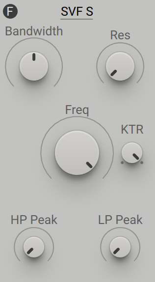 |
Freq: Adjusts the cutoff frequencies of the two serial filters. Both cutoff frequencies are offset by the same amount. Their relative position in the frequency position is set with the Bandwidth control.
Res: Adjusts the resonance amount of the low-pass filter. Turning Res to the right increases the resonance, causing the frequency content at the cutoff frequencies to become more pronounced.
Bandwidth: Spreads the cutoff frequencies of the two serial filters in the frequency spectrum. At minimum setting, both filters share the same cutoff frequency. As Bandwidth is increased, the high-pass filter's cutoff moves down in frequency, while the low-pass filter's cutoff moves up. This way you can distribute the filter resonances to create formant frequencies.
KTR: Adjusts the amount of key tracking, which is the degree to which the filter's cutoff frequency follows the MIDI pitch.
HP Peak: Gradually turns the high-pass filter into a peak filter (a band-pass filter mixed with the input signal) with only a resonant peak but no filter slope. This way you can add formant frequencies without filtering out the rest of a signal.
LP Peak: Gradually turns the low-pass filter into a peak filter (a band-pass filter mixed with the input signal) with only a resonant peak but no filter slope. This way you can add formant frequencies without filtering out the rest of a signal.
Tip
You can use the Exciter envelope via the Modulation sources on the Routing page to briefly trigger self-oscillation of the SVF Serial at high Res settings. This so called filter pinging produces damped sine waves that can be played via MIDI by using key tracking (KTR).