Wave page
The Wave page of Absynth 6 provides intuitive tools to shape your custom waveforms based on factory waveforms or created from scratch.
The Wave page of Absynth 6 provides intuitive tools to shape your user waveforms. User waveforms can be based on factory waveforms or created from scratch. You can use these waveforms in various places in the instrument, including many modules and the LFOs. User waveforms are saved with each preset and are available only in this preset. However you can reuse waveforms from other presets using copy/paste.
To open the Wave page, click the Wave button at the top of the Absynth 6 window:

Note
The Wave page opens automatically when you click Edit or New in a Waveform selector. Waveform selectors are available in various modules of the Patch page, as well as in the LFOs configured in the LFO page and Envelope page.
The Wave page contains the following areas:
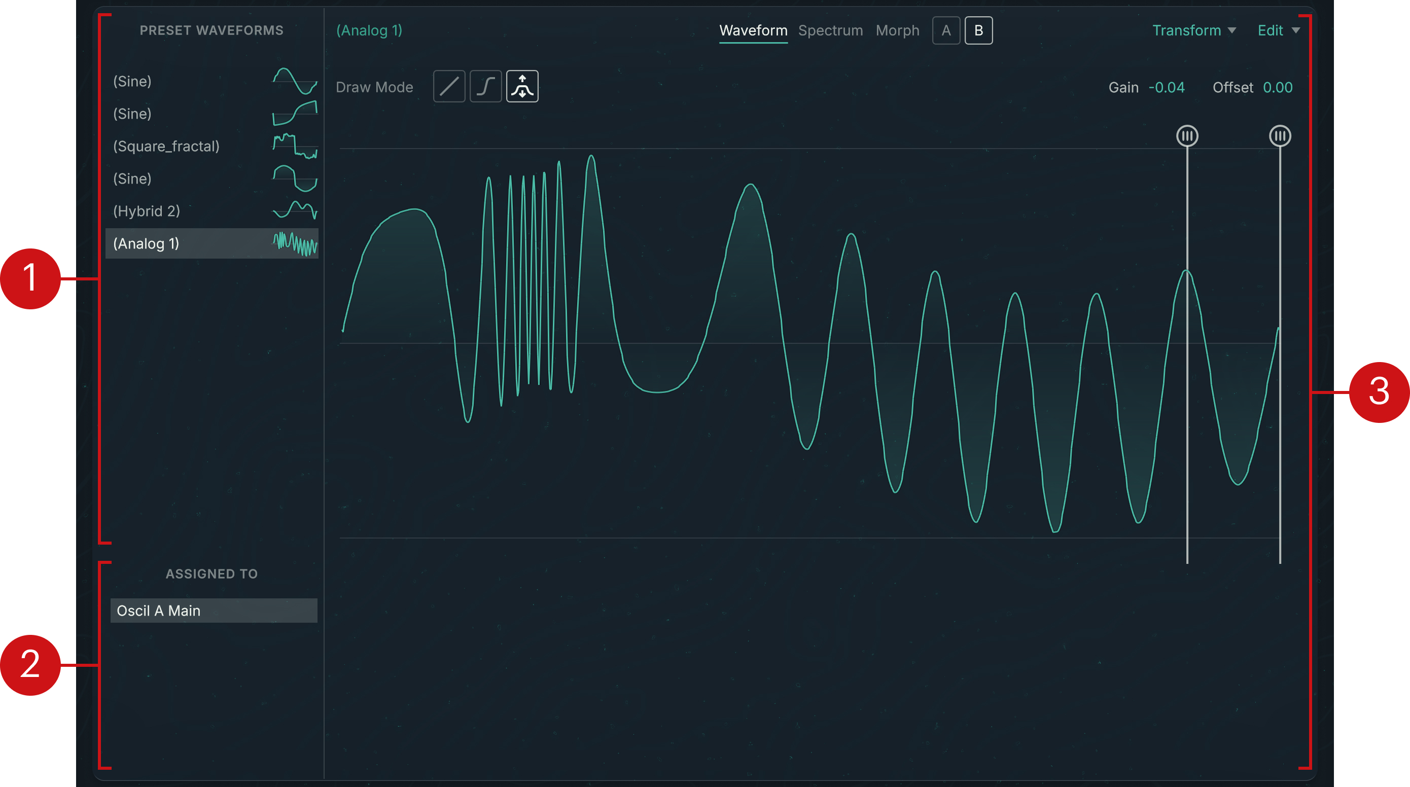
Preset Waveforms list: Displays all the user waveforms in the preset. Each entry shows the waveform name and a thumbnail of its shape. Selecting an entry will open the waveform in the Waveform Editor on the right. User waveforms always have brackets around their name to easily distinguish them from factory waveforms in the Waveform selectors. By default, a user waveform takes the name of the waveform from which it is coming. You can rename it by double-clicking its entry and typing a new name from your computer keyboard.
Note
User waveforms are always created by starting from an existing waveform, as described in Waveform selector.
Assigned To list: Shows the component(s) using the selected waveform.
Waveform Editor: Displays and lets you modify the selected waveform. You can find more information in Waveform Editor.
Waveform Editor
The Waveform Editor is the main area of the Wave page. It lets you adjust the user waveform selected in the PRESET WAVEFORMS list on the left. The Waveform Editor provides different views that focus on different aspects of the waveform.
At the top of the Waveform Editor, the Waveform View selector lets you switch between the following views:
 |
Waveform: Shows the Waveform view, which lets you edit the waveform in the time domain.
Spectrum: Shows the Spectrum view, which lets you edit the waveform in the frequency domain.
Morph (only available for Morph waveforms): Shows the Morph view, where you can configure the morphing between both waveforms.
Waveform view
The Waveform view lets you shape the selected waveform in the time domain. It contains the following controls:
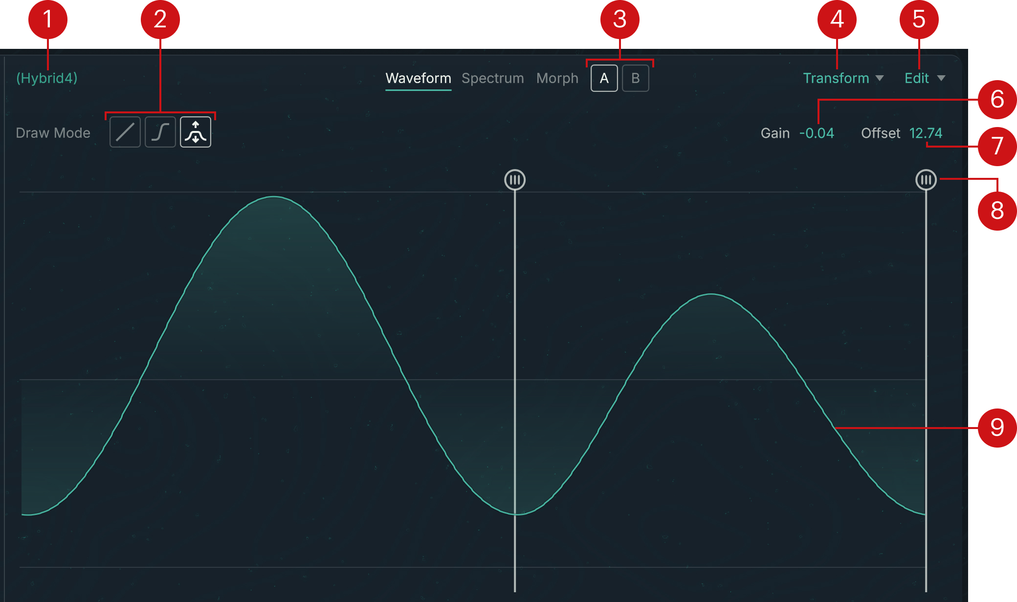 |
Waveform name
Draw Mode selector: Switches between three graphical modes for shaping the waveform with your mouse. The available modes are, from left to right:
Line mode: Builds the waveform with straight lines. The line starts from the Anchor point (marked by a vertical bar through the waveform display) and ends where you click. At every click, the Anchor point jumps to the clicked position and you can directly shape the next segment from there.
Curve mode: Works like the Line mode but inserts semi-cosine curves instead of straight lines. This results in smoother transitions between segments, which can help attenuate harsh high frequency contents.
Stretch mode: When you select this mode, a second Anchor point appears in the waveform display. Clicking and dragging your mouse vertically lets you expand or compress the part of the waveform between the Anchor points. You can drag the handles at the top of the bars to select another part of the waveform.
1/2 switch (Morph waveforms only): Selects either of the base waveforms for editing.
Transform menu: Lets you apply various transformations to the waveform. You can find more information in Transform menu (Waveform view).
Edit menu: Provides copy/paste commands for waveforms. Selecting Copy Waveform stores the current waveform into the clipboard. You can then select Paste Waveform in another waveform to replace it with the copied waveform.
Gain: Adjusts the waveform’s amplification level in dB.
Offset: Adjusts the amplitude offset of the waveform relative to the x-axis (0 dB). With Offset at 0 dB, the highest and lowest points of the waveform are at the same distance from the x-axis.
Anchor point: Defines a reference point on the waveform when using one of the drawing modes. Line mode and Curve mode use one Anchor point, while Stretch mode uses two. You can move the Anchor point(s) by dragging the top handle horizontally with your mouse.
Waveform shape: Represents the current waveform. Any edits that you make using the mouse, the functions from the Transform menu, or the copy/paste commands, will be directly mirrored in the display and in the resulting sound.
Transform menu (Waveform view)
The Transform menu lets you apply various transformations to the displayed waveform. In the menu, the transformations are split into two main groups:
 |
The transformations from the upper group are directly applied to the waveform, whereas the transformations from the lower group open a dedicated Transform panel with additional settings at the top of the page:
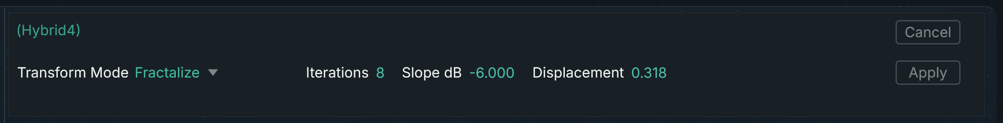 |
In the Transform panel the following elements are common to all transformations:
Transform Mode menu: Switches to another transformation.
Cancel: Closes the panel and leaves the original waveform untouched.
Apply: Transforms the original waveform according to the panel settings and closes the panel.
The other parameters in the Transform panel depend on the selected transformation. As you change the parameter values, the waveform display and the resulting sound are updated in real time to show you the effect of your actions. You can then choose to apply these changes or to cancel them.
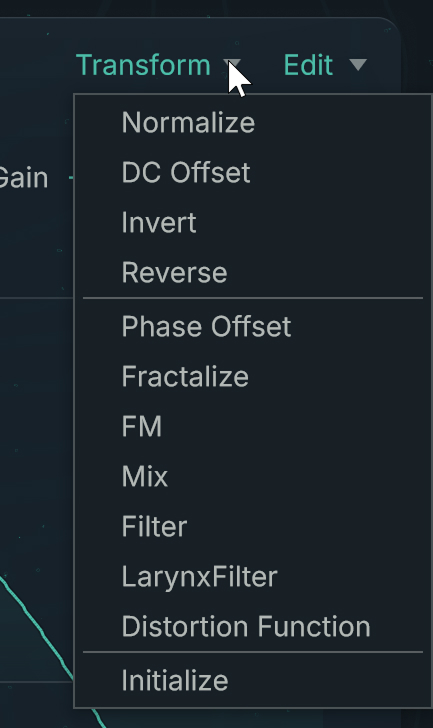
The Transform menu of the Waveform view provides the following transformations:
Normalize: Normalizes the waveform amplitude. The waveform’s minimum and maximum values are adjusted to the maximum value range.
DC Offset: Adjusts the amplitude offset of the waveform so that the waveform’s energy will be evenly distributed between its positive and negative sections, which can help avoid unwanted audio artifacts. This is different from centering the waveform by setting the Offset control to zero.
Invert: Flips the waveform vertically (effectively inverting the waveform’s phase).
Reverse: Flips the waveform horizontally.
Phase Offset: Lets you adjust the phase of the waveform. In the Transform panel that opens, the Offset parameter adjusts the phase offset.
Fractalize: Adds smaller copies of the waveform to the waveform itself, so that parts of the waveform become similar to the shape of the whole. You can use it to add overtones to the waveform. This allows for extraordinary waveform manipulations and is particularly good for creating powerful, organic waveforms. The Transform panel opens and provides the following parameters:
Iterations: Selects how many times the waveform is copied to itself, which affects the quantity of details added to the original waveform. The value range is between 2 and 8. Higher values lead to more complex, lighter-sounding sounds.
Slope dB: Adjusts the mixing relationship between the original waveform and its copies. This controls the fractalization’s intensity: The higher the value, the richer the sound in overtones and noise.
Displacement: Defines the shift of the copied area relative to the original waveform: 0 corresponds to a position before the waveform, 1 to a position after the waveform. With a value of 0.5, the area is in the center of the waveform. Modulating this parameter with an LFO or an envelope can produce interesting movements inside the sound.
FM: Applies frequency modulation. The current waveform acts as the carrier. The Transform panel opens and provides the following parameters:
Modulation waveform: Shows the name of the waveform used as modulator. By default the Sine waveform is selected. Clicking the name opens a Waveform selector where you can choose another modulation waveform.
Amount: Determines the intensity of the frequency modulation.
Main Freq: Defines the denominator of the frequency ratio between modulator and carrier.
Mod Freq: Defines the numerator of the frequency ratio between modulator and carrier.
Phase: Adjusts the phase of the modulator relative to the carrier.
Mix: Mixes the waveform with another one. In the Transform panel that opens, your original waveform is labeled A and the additional waveform is labeled B. The panel provides the following parameters:
Mix waveform: Shows the name of the waveform mixed with the original one. By default the Sine waveform is selected. Clicking the name opens a Waveform selector where you can choose another waveform.
Mix A: Adjusts the level of the original waveform.
Mix B: Adjusts the level of the additional waveform.
Freq Ratio B: Adjusts the frequency ratio between the additional waveform and the original waveform.
Phase B: Adjusts the phase of the additional waveform relative to the original waveform.
Phase Invert switch (phase symbol): Inverts the phase of the additional waveform.
Filter: Applies a filter to the waveform. The Transform panel opens and provides the following parameters:
LP/HP/BP: Selects between low-pass (LP), high-pass (HP), and band-pass (BP) filtering.
Frequency: Adjusts the cutoff frequency of the filter.
Resonance: Adjusts the resonance at the cutoff frequency.
Larynx Filter: Simulates the resonant frequencies of the human vocal tract as it produces different vowels. Each vowel has its own set of characteristic frequencies, called formants. The Transform panel opens and provides the following parameters:
Vowel: Selects from different vowel models, each having a distinct set of formants.
Resonance: Adjusts the global resonance of the filter.
Shift: Adjusts the frequencies of all the formants simultaneously while maintaining the frequency ratios between the formants. This modifies the perceived timbre of the voice without affecting the global pitch of the vowel.
Distortion Function: Applies an adjustable distortion function to the waveform. The Transform panel opens and provides the following parameters:
Amount: Adjusts the distortion strength.
Asymmetry: Adjusts a distinct distortion for the positive values and for the negative values. At the minimum value 0, the distortion is the same on both sides. At the maximum value 1, only one side is distorted.
Mix: Adjusts the balance between the original signal and the distortion output.
Phase Invert: Inverts the phase of the distortion function.
Initialize: Resets the waveform to zero.
Spectrum view
The Spectrum view of the Wave page lets you shape the selected waveform in the frequency domain. It shows the first 512 harmonics of the selected waveform as a series of bars: The colored bars in the top half show the harmonics’ amplitudes, and the white bars in the lower half show their phases. The fundamental frequency, also called first harmonic, is represented by the first pair of colored and white bars at full left, followed on its right by the higher harmonics in ascending order.
The Spectrum view contains the following controls:
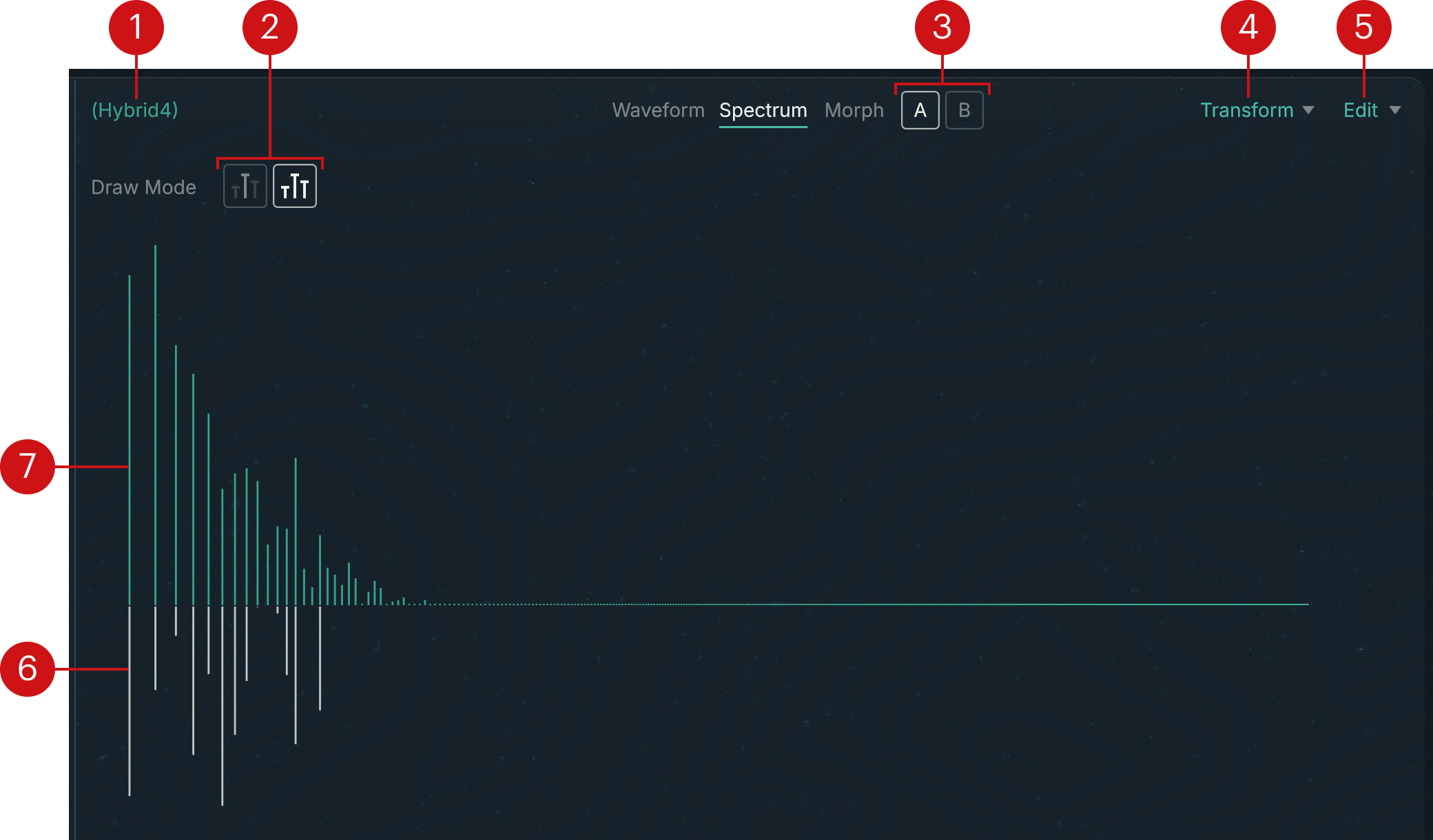 |
Waveform name
Draw Mode selector: Switches between two graphical modes for editing the harmonics with your mouse. The available modes are, from left to right:
Single Harmonic mode: In this mode you can click a bar and drag your mouse to adjust the height of this particular bar only. The horizontal movements of the mouse have no effect, and its vertical movements are applied relative to the bar’s current height. This mode can be used for precise manipulations.
Multi Harmonics mode: In this mode you can click anywhere in the display and drag your mouse to draw the amplitudes or the phases of multiple harmonics in one go. As you drag the mouse, each bar under the mouse cursor will be set to the exact height of the cursor. Depending on whether you first clicked in the upper half or in the lower half of the display, your mouse movements will affect only the amplitudes or only the phases of the harmonics.
1/2 switch (Morph waveforms only): Selects either of the base waveforms for editing.
Transform menu: Lets you apply various transformations to the spectrum. You can find more information in Transform menu (Spectrum view).
Edit menu: Provides copy/paste commands for waveforms. Selecting Copy Waveform stores the current waveform into the clipboard. You can then select Paste Waveform in another waveform to replace it with the copied waveform.
Phase bars: The white bars in the lower half of the display represent the phases of the harmonics. The zero is on the middle line and the phase values grow downwards.
Amplitude bars: The colored bars in the upper half of the display represent the amplitudes of the harmonics. The zero is on the middle line and the amplitude values grows upwards.
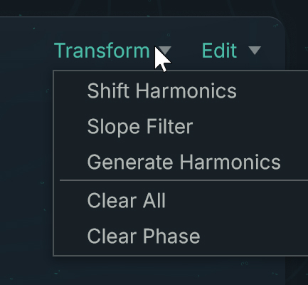
Transform menu (Spectrum view)
The Transform menu lets you apply various transformations to the displayed spectrum. In the menu, the transformations are split into two groups:
 |
The transformations from the lower group are directly applied to the spectrum, whereas the transformations from the upper group open a dedicated Transform panel with additional settings at the top of the page:
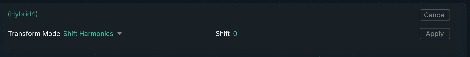 |
In the Transform panel the following elements are common to all transformations:
Transform Mode menu: Switches to another transformation.
Cancel: Closes the panel and leaves the original spectrum untouched.
Apply: Transforms the original spectrum according to the panel settings and closes the panel.
The other parameters in the Transform panel depend on the selected transformation. As you change the parameter values, the spectrum display and the resulting sound are updated in real time to show you the effect of your actions. You can then choose to apply these changes or to cancel them.
The Transform menu of the Spectrum view provides the following transformations:
Shift Harmonics: Shifts all the harmonics to the left or to the right. The Transform panel opens with a single Shift parameter, which adjusts how far the harmonics will be shifted. Negative values of Shift will move the harmonics to the left (lower frequencies), positive values will move them to the right (higher frequencies). The available values range from -64 to 64.
Slope Filter: Progressively attenuates or amplifies the harmonics on either side of a particular harmonic called crossover harmonic. The attenuation/amplification of the other harmonics grows with their distance to crossover harmonic. You can adjust each side independently. The Transform panel opens and provides the following parameters:
Crossover: Specifies the harmonic used as central point. The remaining harmonics will be amplified or attenuated on either side independently.
Low dB per Octave: Adjusts the slope of the attenuation or amplification for the harmonics lower than the crossover harmonic (on its left in the display).
High dB per Octave: Adjusts the slope of the attenuation or amplification for the harmonics higher than the crossover harmonic (on its rightin the display).
Generate Harmonics: Creates a series of harmonics with a decreasing slope. The Transform panel opens and provides the following parameters:
Slope dB: Adjusts how fast the amplitudes decrease in the series.
Balance: Adjusts the mix between the original spectrum (Balance set to 0) and the generated series (Balance set to 1).
Series Mult: Includes only specific multiples in the generated series: For example, setting Series Mult to 2 will generate only the 2nd, 4th, 6th, (…) harmonics, while setting it to 3 will generate only the 3rd, 6th, 9th, (…) harmonics.
Series +/-: Adjusts the starting harmonic in the series. Changing this value results in shifting the entire series to the next or previous harmonics. For example, this can be useful to bring back the fundamental into a series including only specific multiples.
Clear All: Removes all the harmonics from the spectrum except the first one (the fundamental frequency).
Clear Phase: Clears all the phase bars from the spectrum while leaving the amplitude bars untouched. This aligns the phases of all harmonics.
Morph view
The Morph view of the Wave page is available only when a morph waveform is selected in the PRESET WAVEFORMS list on the left. The Morph view lets you adjust the waveform’s morphing in detail.
A morph waveform allows you to dynamically blend two waveforms into one. You can edit each of the base waveforms using the tools in the Waveform view and Spectrum view, and configure how they are morphed using the Morph view.
The Morph view contains the following elements:
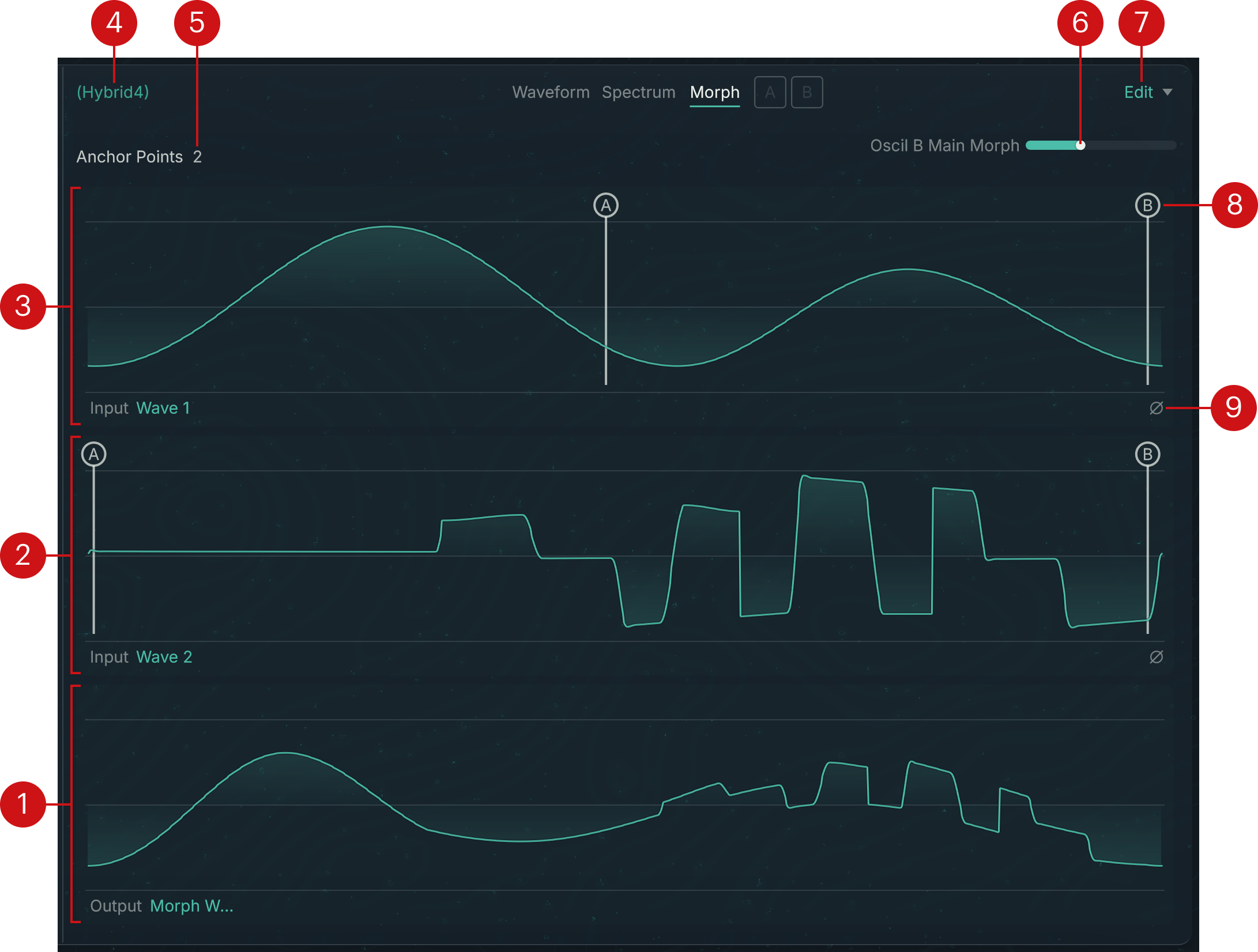 |
Morph Wave display: Shows the waveform shape resulting from the morphing. The shape changes as you move the Morph slider at the top right, and when you modify the position of the various Anchor points in the Wave 1 and Wave 2 waveforms above.
Wave 2 display: Shows the shape of the second base waveform.
Wave 1 display: Shows the shape of the first base waveform.
Waveform name
Anchor Points menu: Selects the number of Anchor points used by the morphing. You can choose between 2, 3, and 4 Anchor points. These Anchor points will appear as vertical bars labeled A, B, C, and D in the Wave 1 and Wave 2 displays.
Morph slider: Adjusts the morphing ratio between the two base waveforms. With the slider at full left, the morph wave mirrors Wave 1. With the slider at full right, the morph wave mirrors Wave 2. In other words, the Morph parameter describes the position of the morph waveform on the way from Wave 1 to Wave 2.
Edit menu: Provides copy/paste commands for waveforms. Selecting Copy Waveform stores the current waveform into the clipboard. You can then select Paste Waveform in another waveform to replace it with the copied waveform.
Anchor points: These points define references for the morphing. Each Anchor point in Wave 1 is linked to the point with the same letter in Wave 2, so that the segment between two Anchor points, for example A and B, in Wave 1 will be morphed into the segment between the same Anchor points A and B in Wave 2. You can move the Anchor points by dragging their letter horizontally with your mouse. Matching different segments from the two base waveforms can produce interesting effects in the morph waveform and makes morphing a subtle design tool.
Phase Invert button (phase symbol): Inverts the phase of that waveform.