Patch page
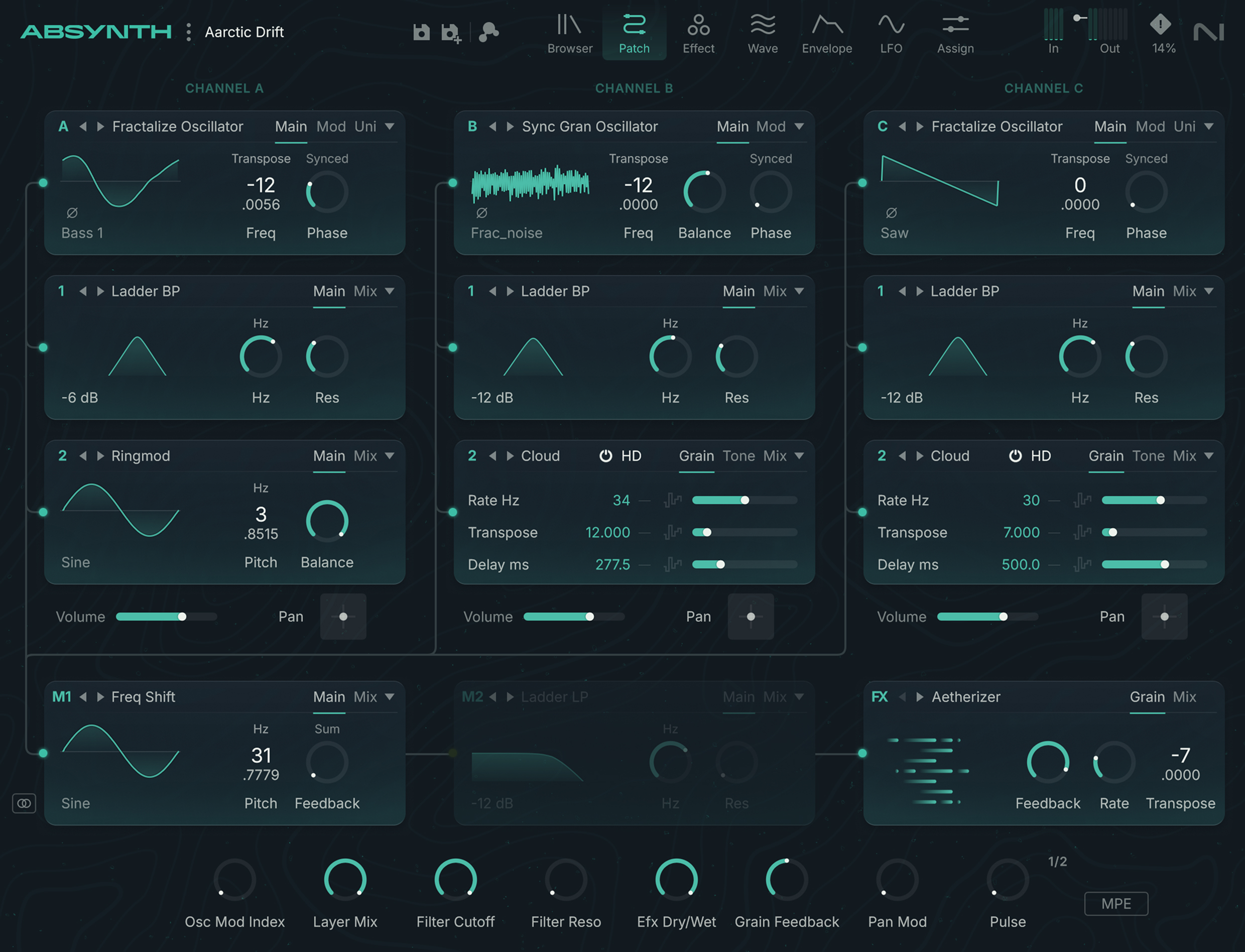
The Patch page of Absynth 6 lets you assemble the components that will generate the preset’s sound.
The Patch page of Absynth 6 lets you assemble the components that will generate the preset’s sound.
To open the Patch page, click the Patch button at the top of the Absynth 6 window:

The modules represent the individual components in the Patch page. There are different types of modules: For example, the Oscillator modules are sound sources, while the Modulator, Filter, and Waveshaper modules process existing sounds. The semi-modular design of Absynth 6 allows you to choose the arrangement of some of the modules, while other modules have a fixed place in the signal flow.
Patch basics
The patch is structured into four channels: The signals start on three distinct Oscillator channels, then they are combined on the Main channel.
Oscillator channels
Absynth 6 provides three so-called Oscillator channels labeled Channel A, Channel B, and Channel C, and laid out vertically in the top part of the Patch page:
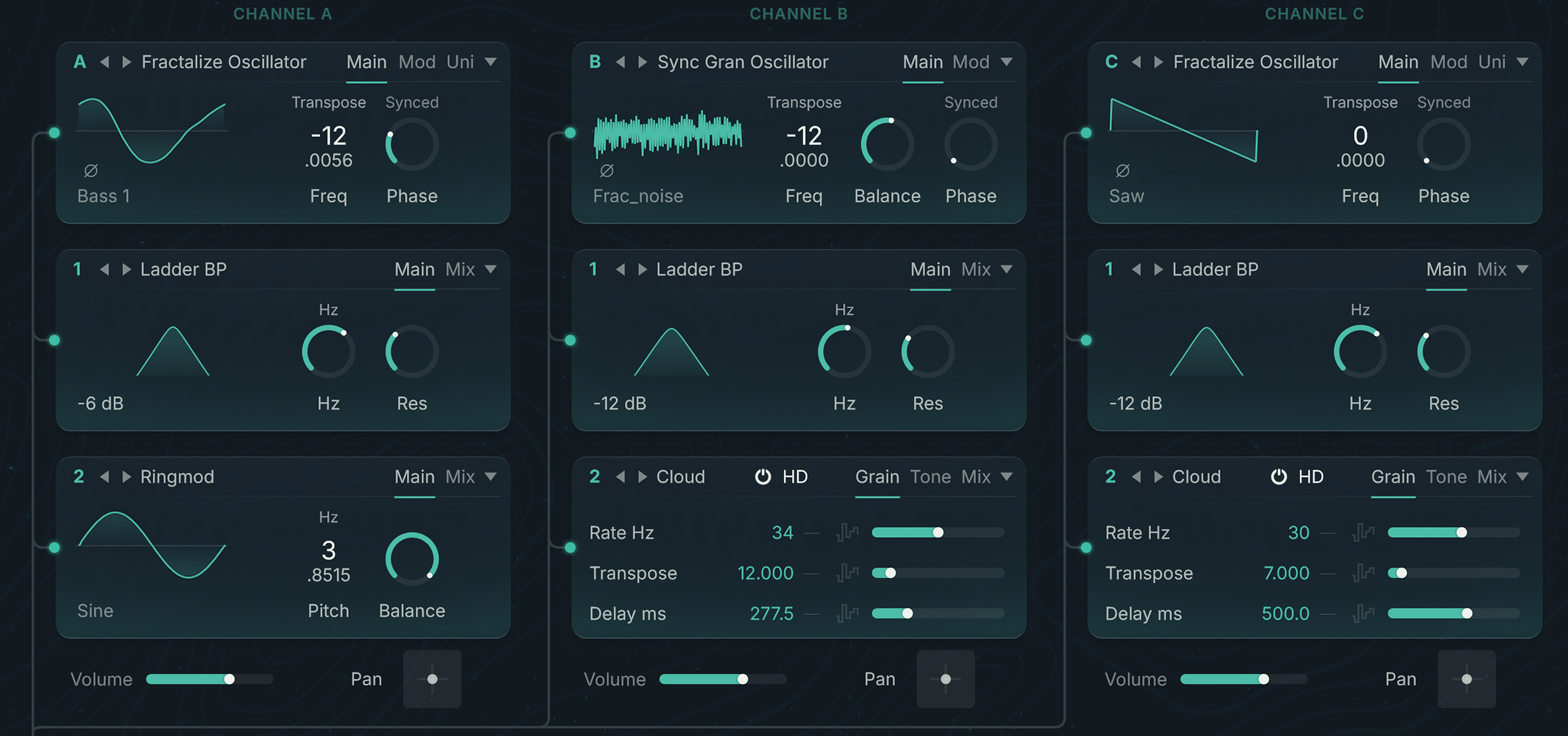
Each channel can contain up to three modules. The signal flows from top to bottom:
The first module at the top is always a source module (sometimes globally referred to as Oscillator). Labeled A, B, and C, the source modules are the only sound sources in Absynth 6 and provide the sonic foundation for every preset. If you deactivate a source module, its entire channel turns off. Three categories of source modules are available: Oscillators, Samplers, and the Audio Input.
The two modules below are insert modules. Labeled 1 and 2, they process the sound coming from the previous module. Three categories of insert modules are available: Filters, Modulators, and the Waveshaper.
Elsewhere in the Absynth interface, the modules of the Oscillator channels are referred to using their channel letter and their position within the channel. For example:
Oscil A would refer to the source module on channel A,
Filter B1 would refer to the Filter used as first insert module on channel B,
WS C2 would refer to the Waveshaper used as second insert module on channel C.
Channel levels
At the bottom of the Oscillator channels, the three Volume sliders let you adjust the level of the respective channels:

Surround panning the channels
Located in the lower left corner of the Patch page, the Surround Pan switch lets you to activate or deactivate the Surround Pan mode.
 |
In Surround Pan mode you can freely position the sound of each Oscillator channel in the surround field using the Pan X-Y control right of the Volume slider, at the bottom of the channel:
 |
Main channel
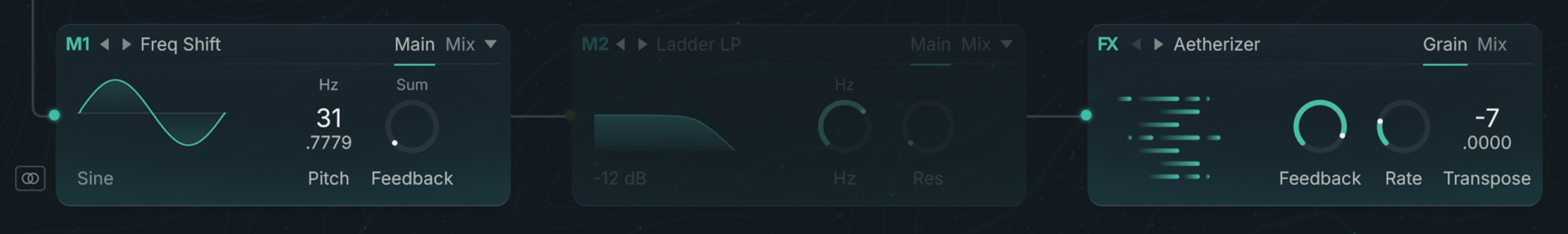
The signals from the three Oscillator channels are mixed into the Main channel, which is arranged horizontally at the bottom of the Patch page. In the Main channel, the signal flows from left to right through three modules:
The first two modules on the left are insert modules. Labeled M1 and M2 (for “Main 1” and “Main 2”), they process the sound coming from the three Oscillator channels above. You can use the same insert modules as in the Oscillator channels: Filters, Modulators, and the Waveshaper.
The last module on the right is an effect module. Labeled FX, it is at the end of the module chain and its output signal leaves Absynth 6. You can choose from a set of advanced effects and adjust their most important parameters directly from the module. The detailed configuration of the effects takes place in the dedicated Effect page.
Monophonic and Polyphonic modes
The insert modules of the Main channel have two operating modes:
In Monophonic mode, the signals from the three Oscillator channels are mixed beforehand and the module processes the mix.
In Polyphonic mode, the module processes the signal from each Oscillator channel separately.
You can switch an insert module between both modes from the module’s Edit menu.
Note
If the first insert module is set to Monophonic mode, the second insert module cannot operate in Polyphonic mode, since the first module has already summed the three Oscillator signals beforehand.
The difference between the two modes can be heard particularly clearly in the Waveshaper module: In Polyphonic mode every voice has its own, independent Waveshaper. The distortion affects every voice separately. In Monophonic mode, a single Waveshaper processes the different voices, which means that many of the played notes will interact. You can try out the effect by inserting a Waveshaper module into the Main channel. Play a couple of sounds while switching between both modes: You will notice that the Monophonic mode reacts with a significantly stronger distortion as you begin to play multiple notes. This is because the signals of the different voices are assembled before the Waveshaper input, which results in a higher input gauge. In Polyphonic mode, by contrast, the voices are distributed among multiple Waveshapers and produce lower signal levels.
Tip
For low level input signals, the Waveshaper in Monophonic mode works like a compressor and lends itself well to compressing and warming up the input signal.
Working with modules
The various modules available in the Patch page share a common layout and a set of generic features and workflows:
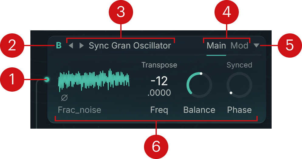 |
Connector dot: Clicking the dot activates or deactivates the module. The audio signal path is depicted by wires connecting the dots of the active modules. Inactive modules are grayed out and their dots are bypassed. On channel A–C, deactivating the source module deactivates the whole channel, and on an inactive channel, activating any of its module reactivates the entire channel.
Note
When a module is active, you can click anywhere on its left border to deactivate it. When a module is inactive, you can click anywhere in the module to activate it.
Module label: Identifies the module. The letter A, B, or C indicates the source module of the corresponding Oscillator channel, 1 and 2 indicate the first and second insert modules of an Oscillator channel, M1 and M2 indicate the first and second insert modules of the Main channel, and FX indicates the effect module at the end of the module chain.
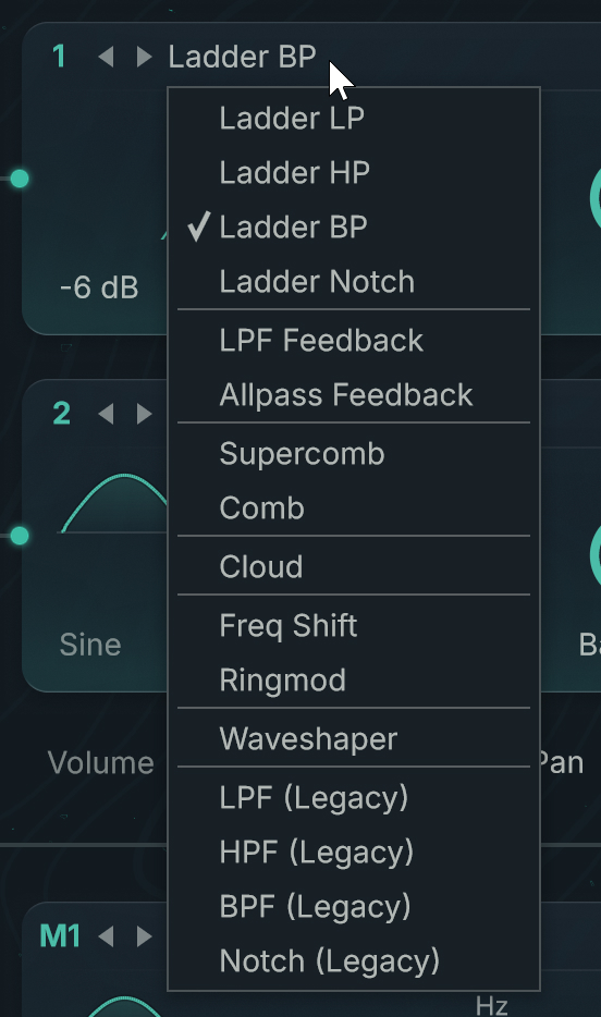
Type selector: Shows the module type. Clicking the type name opens a menu from which you can switch the module to another type. You can also click the left/right arrows to switch to the previous or next type. The entries available in the Type menu vary with the role of the module (source, insert, or effect module).
Panel tabs: Clicking either tab shows the corresponding panel of parameters below.
The available panels depend on the type of module (Oscillator, Filter, Modulator or Waveshaper) as well as on the specific mode for each module type. You will find a complete list of available panels in the module-specific sections.
Edit menu (downward arrow): Provides editing functions like copy/paste commands and Mutation shortcuts. The exact menu entries vary with the module’s role (source or insert) and channel (Oscillator channel or Main channel).
Note
The effect module has no Edit menu.
Parameter panel: A module can have up to three panels organizing the module parameters. Each panel can be called by clicking the corresponding tab at the top right. In most modules the left part of the Main panel shows a graphic display that visually illustrates the type of module, its function, or the selected waveform.
Waveform selector
Waveforms are used in many parts of Absynth. Each time, the Waveform selector lets you choose the desired waveform.
In the Patch page, the Waveform selector is available in the following modules:
Source modules: all the Oscillators.
Insert modules: the Modulators (Freq Shift and Ringmod), the Waveshaper, and the Filters providing a feedback loop (LPF Feedback, Allpass Feedback, and Supercomb).
Note
The Waveform selector is also used in the LFO page, in the LFO controls of the Envelope page, as well as in the Transform panel for the FM and Mix transformations available in the Waveform view of the Wave page.
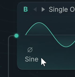
To open the Waveform selector in a module, click the waveform name under the mini waveform display in the module parameters:
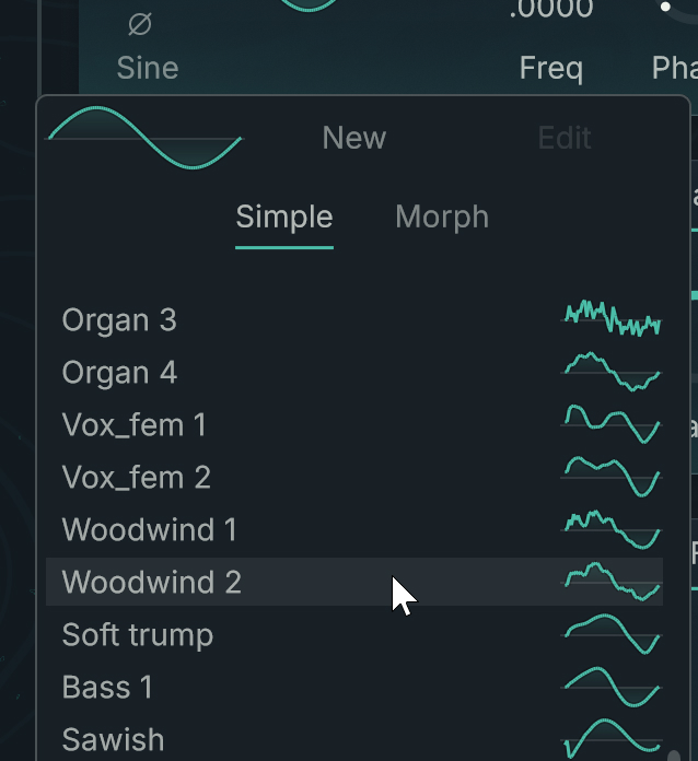
The Waveform selector contains a list with all the available waveforms:
 |
In the list, the names between brackets indicate user-created waveforms.
To load a waveform:
To load a waveform, click its entry in the list.
The new waveform becomes immediately active and you can hear its effect on the sound when you press a key on your MIDI keyboard. The Waveform selector stays open so that you can test different waveforms.
When you are done, click anywhere outside the Waveform selector to close it.
At the top of the Waveform selector, you can also use the following buttons:
Simple: Shows the list of simple waveforms. In this category, next to the standard forms like Sine, Triangle, Saw, orSquare, you also find instrumental and atonal waveforms.
Morph: Shows the list of morph waveforms. A morph waveform contains in fact two waveforms, which you can seamlessly blend (“morph”) with one another.
New: Creates a new user waveform based on the simple or morph waveform currently selected. Absynth automatically switches to the Wave page and selects this new waveform so that you can further edit it.
Edit: This button is available only if a user waveform is selected in the list, which is indicated by the brackets around the name. Clicking Edit switches to the Wave page and selects this user waveform so that you can modify it.
Source modules
The source modules can be loaded in the first slot at the top of the channels A, B, and C. The source modules are the only sound sources in Absynth. The other modules will modify the sounds produced by the source modules.
The source modules can use different types of synthesis, which are grouped into three categories:
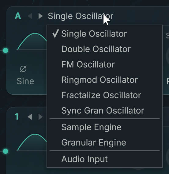
Oscillators are based on monocyclic waveforms played repeatedly to create a musical tone. The following types of Oscillators are available: Single Oscillator, Double Oscillator, FM Oscillator, Ringmod Oscillator, Fractalize Oscillator, and Sync Granular Oscillator.
Samplers can play an audio recording in various ways. The following types of Samplers are available: Sample Engine and Granular Engine.
The Audio Input module does not generate any audio by itself, instead it receives external audio and pass it on to the next modules.
You can choose the type of source module from the Type selector at the top of the first slots:
 |
Edit menu for source modules
The Edit menu of a source module contains the following entries:
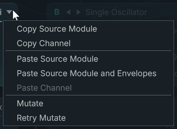 |
Copy Source Module: Copies the settings of the module to the clipboard.
Copy Channel: Copies the settings of all the active modules in that channel to the clipboard.
Paste Source Module: Pastes into the source module the settings stored in the clipboard (using the command Copy Source Module).
Paste Source Module and Envelopes: Pastes into the source module the settings stored in the clipboard (using the command Copy Source Module). Any envelopes linked to the copied source module are also inserted.
Paste Channel: Pastes into the current channel the settings stored in the clipboard.
Mutate: Mutates this particular module.
Retry Mutate: Retries a mutation of the module. This entry is available only if you have already triggered a mutation in this session.
The Mutate and Retry Mutate commands use the mutation settings defined in the Mutator section of the Browser page.
Uni panel (Unisono)
The Uni panel (Unisono) is available for all the Oscillators except the Sync Granular Oscillator. The panel lets you quickly “stack” voices to produce fuller, stronger sounds.
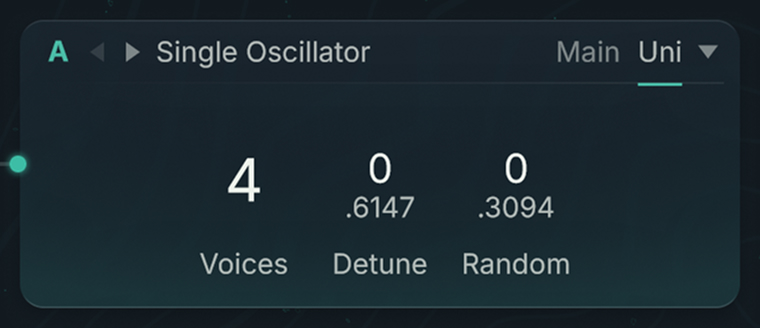 |
The Uni panel contains the following parameters:
Voices: Sets the number of voices produced by each note played. The highest value is 8.
Detune: Adjusts the amount of detuning (in semitones) between the original voice and the additional voices. This parameter is available only if the Voices value is larger than 1, in other words, if there are some additional voices to detune. Even-numbered additional voices are transposed downwards, odd-numbered voices upwards.
Random: Adjusts the amount of additional, random detuning (upwards and downwards) in semitones. The random detuning of the voices occurs with every note in the sequence. Subtly put to work, with a low Voices value, Random can produce the effect of a sloppy or imprecise intonation (for example, in order to imitate a string instrument without tension or to give atonal percussion sounds some natural variation). You can get some unpredictable and exciting results by playing around with different selections of notes.
Single Oscillator
The Single Oscillator is the simplest source module. It includes only one oscillator.
The Main panel contains the parameters for the main oscillator:
Mini Waveform: Shows the shape and the name of the loaded waveform. If a Morph waveform is loaded, you can click the shape and drag your mouse vertically to morph the waveform. Clicking the waveform name opens the Waveform selector and lets you choose another waveform.
Phase Invert button (phase symbol): Above the waveform name, the Phase Invert button lets you reverse the phase of the signal generated by the oscillator.
Frequency menu and control (Freq): These controls let you to define the oscillator’s frequency as a transposition of the played note (Transpose), as a relationship with the played note (Ratio), as a fixed frequency (Hz), or as a fixed MIDI note number (Note). You can find more information in Frequency menu and control.
Phase Sync switch: Setting the switch to Synced will reset the phase of the oscillator with every incoming MIDI note. When the Phase Sync switch is set to Fr Free, the oscillator will not be reset. When only one oscillator is active and you have set a single voice in the Uni panel, the mode Free has almost no effect. When you have a higher Unisono number of voices or multiple active oscillators, every note leads to an audible change in the sound.
Phase: Sets the phase of the oscillator. This control is available only when the Phase Sync switch is set to Synced. The effect of the Phase control is only audible if a second oscillator is active. This parameter is useful when using integer values for frequency ratios between carrier and modulator, as it is the case in FM.
The Uni panel is common to most Oscillators and is described in Uni panel (Unisono).
Double Oscillator
The Double Oscillator contains two oscillators: the Main oscillator and the Mod oscillator (for “modulation”). The signals of the two oscillators are mixed.
The Main panel contains the same parameters as the Single Oscillator with an additional Balance control:
Mini Waveform: Shows the shape and the name of the loaded waveform. If a Morph waveform is loaded, you can click the shape and drag your mouse vertically to morph the waveform. Clicking the waveform name opens the Waveform selector and lets you choose another waveform.
Phase Invert button (phase symbol): Above the waveform name, the Phase Invert button lets you reverse the phase of the signal generated by the oscillator.
Frequency menu and control (Freq): These controls let you to define the oscillator’s frequency as a transposition of the played note (Transpose), as a relationship with the played note (Ratio), as a fixed frequency (Hz), or as a fixed MIDI note number (Note). You can find more information in Frequency menu and control.
Balance control: Adjusts the balance between the Main and Mod oscillators in the output signal.
Phase Sync switch: Setting the switch to Synced will reset the phase of the oscillator with every incoming MIDI note. When the Phase Sync switch is set to Fr Free, the oscillator will not be reset. When only one oscillator is active and you have set a single voice in the Uni panel, the mode Free has almost no effect. When you have a higher Unisono number of voices or multiple active oscillators, every note leads to an audible change in the sound.
Phase: Sets the phase of the oscillator. This control is available only when the Phase Sync switch is set to Synced. The effect of the Phase control is only audible if a second oscillator is active. This parameter is useful when using integer values for frequency ratios between carrier and modulator, as it is the case in FM.
The Mod panel contains the parameters of the modulating oscillator:
Mini Waveform: Shows the shape and the name of the loaded waveform. If a Morph waveform is loaded, you can click the shape and drag your mouse vertically to morph the waveform. Clicking the waveform name opens the Waveform selector and lets you choose another waveform.
Frequency menu and control (Freq): These controls let you to define the oscillator’s frequency as a transposition of the played note (Transpose), as a relationship with the played note (Ratio), as a fixed frequency (Hz), or as a fixed MIDI note number (Note). You can find more information in Frequency menu and control.
Phase: Sets the phase of the oscillator. This control is available only when the Phase Sync switch is set to Synced. The effect of the Phase control is only audible if a second oscillator is active. This parameter is useful when using integer values for frequency ratios between carrier and modulator, as it is the case in FM.
The Uni panel is common to most Oscillators and is described in Uni panel (Unisono).
Note
A Double Oscillator uses less CPU resources than two Single Oscillators.
FM Oscillator
Frequency modulation was discovered in the late 1960’s by John Chowning and achieved great popularity in the 1980’s through Yamaha’s DX7 synthesizer. Much has already been written about FM synthesis so we will not go into detail here.
In the FM Oscillator, the Mod oscillator modulates the frequency of the Main oscillator.
The Main panel contains the same parameters as the Single Oscillator with an additional FM Index control:
Mini Waveform: Shows the shape and the name of the loaded waveform. If a Morph waveform is loaded, you can click the shape and drag your mouse vertically to morph the waveform. Clicking the waveform name opens the Waveform selector and lets you choose another waveform.
Phase Invert button (phase symbol): Above the waveform name, the Phase Invert button lets you reverse the phase of the signal generated by the oscillator.
Frequency menu and control (Freq): These controls let you to define the oscillator’s frequency as a transposition of the played note (Transpose), as a relationship with the played note (Ratio), as a fixed frequency (Hz), or as a fixed MIDI note number (Note). You can find more information in Frequency menu and control.
FM Index: Determines the depth of the frequency modulation.
Phase Sync switch: Setting the switch to Synced will reset the phase of the oscillator with every incoming MIDI note. When the Phase Sync switch is set to Fr Free, the oscillator will not be reset. When only one oscillator is active and you have set a single voice in the Uni panel, the mode Free has almost no effect. When you have a higher Unisono number of voices or multiple active oscillators, every note leads to an audible change in the sound.
Phase: Sets the phase of the oscillator. This control is available only when the Phase Sync switch is set to Synced. The effect of the Phase control is only audible if a second oscillator is active. This parameter is useful when using integer values for frequency ratios between carrier and modulator, as it is the case in FM.
The Mod panel contains the parameters of the modulating oscillator:
Mini Waveform: Shows the shape and the name of the loaded waveform. If a Morph waveform is loaded, you can click the shape and drag your mouse vertically to morph the waveform. Clicking the waveform name opens the Waveform selector and lets you choose another waveform.
Frequency menu and control (Freq): These controls let you to define the oscillator’s frequency as a transposition of the played note (Transpose), as a relationship with the played note (Ratio), as a fixed frequency (Hz), or as a fixed MIDI note number (Note). You can find more information in Frequency menu and control.
Phase: Sets the phase of the oscillator. This control is available only when the Phase Sync switch is set to Synced. The effect of the Phase control is only audible if a second oscillator is active. This parameter is useful when using integer values for frequency ratios between carrier and modulator, as it is the case in FM.
The Uni panel is common to most Oscillators and is described in Uni panel (Unisono).
Ringmod Oscillator
In the Ringmod Oscillator, the signals from the Main and Mod oscillators are multiplied with one another.
The Main panel contains the same parameters as the Single Oscillator with an additional Balance control:
Mini Waveform: Shows the shape and the name of the loaded waveform. If a Morph waveform is loaded, you can click the shape and drag your mouse vertically to morph the waveform. Clicking the waveform name opens the Waveform selector and lets you choose another waveform.
Phase Invert button (phase symbol): Above the waveform name, the Phase Invert button lets you reverse the phase of the signal generated by the oscillator.
Frequency menu and control (Freq): These controls let you to define the oscillator’s frequency as a transposition of the played note (Transpose), as a relationship with the played note (Ratio), as a fixed frequency (Hz), or as a fixed MIDI note number (Note). You can find more information in Frequency menu and control.
Balance control: Adjusts the balance between the Main and Mod oscillators in the output signal.
Phase Sync switch: Setting the switch to Synced will reset the phase of the oscillator with every incoming MIDI note. When the Phase Sync switch is set to Fr Free, the oscillator will not be reset. When only one oscillator is active and you have set a single voice in the Uni panel, the mode Free has almost no effect. When you have a higher Unisono number of voices or multiple active oscillators, every note leads to an audible change in the sound.
Phase: Sets the phase of the oscillator. This control is available only when the Phase Sync switch is set to Synced. The effect of the Phase control is only audible if a second oscillator is active. This parameter is useful when using integer values for frequency ratios between carrier and modulator, as it is the case in FM.
The Mod panel contains the parameters of the modulating oscillator:
Mini Waveform: Shows the shape and the name of the loaded waveform. If a Morph waveform is loaded, you can click the shape and drag your mouse vertically to morph the waveform. Clicking the waveform name opens the Waveform selector and lets you choose another waveform.
Frequency menu and control (Freq): These controls let you to define the oscillator’s frequency as a transposition of the played note (Transpose), as a relationship with the played note (Ratio), as a fixed frequency (Hz), or as a fixed MIDI note number (Note). You can find more information in Frequency menu and control.
Phase: Sets the phase of the oscillator. This control is available only when the Phase Sync switch is set to Synced. The effect of the Phase control is only audible if a second oscillator is active. This parameter is useful when using integer values for frequency ratios between carrier and modulator, as it is the case in FM.
The Uni panel is common to most Oscillators and is described in Uni panel (Unisono).
Fractalize Oscillator
Experienced Absynth users will recognize the Fractalize Oscillator as a real time version of the Fractalize function available in the Transform menu of the Wave page. In the Fractalize Oscillator, the selected waveform is copied to itself so that smaller elements of the waveform become similar to the image of the whole. You can use the Fractalize Oscillator to add overtones to a plain waveform.
The Main panel contains the same parameters as the Single Oscillator:
Mini Waveform: Shows the shape and the name of the loaded waveform. If a Morph waveform is loaded, you can click the shape and drag your mouse vertically to morph the waveform. Clicking the waveform name opens the Waveform selector and lets you choose another waveform.
Phase Invert button (phase symbol): Above the waveform name, the Phase Invert button lets you reverse the phase of the signal generated by the oscillator.
Frequency menu and control (Freq): These controls let you to define the oscillator’s frequency as a transposition of the played note (Transpose), as a relationship with the played note (Ratio), as a fixed frequency (Hz), or as a fixed MIDI note number (Note). You can find more information in Frequency menu and control.
Phase Sync switch: Setting the switch to Synced will reset the phase of the oscillator with every incoming MIDI note. When the Phase Sync switch is set to Fr Free, the oscillator will not be reset. When only one oscillator is active and you have set a single voice in the Uni panel, the mode Free has almost no effect. When you have a higher Unisono number of voices or multiple active oscillators, every note leads to an audible change in the sound.
Phase: Sets the phase of the oscillator. This control is available only when the Phase Sync switch is set to Synced. The effect of the Phase control is only audible if a second oscillator is active. This parameter is useful when using integer values for frequency ratios between carrier and modulator, as it is the case in FM.
The Mod panel contains the following parameters:
Iterations: Selects the number of similar repetitions that you want of the same sound, and how much you want to deviate from the original waveform. The value range is between 2 and 7. Higher values lead to more complex, lighter-sounding sounds (and heavier CPU loads).
Warp: Defines the shift of the copied area relative to the original waveform: 0 corresponds to a position before the waveform, 1 to a position after the waveform. With a value of 0.5, the area is in the center of the waveform. Modulating this parameter with an LFO or an envelope can produce interesting movements inside the sound.
Amount: Adjusts the mixing relationship between the original waveform and its copies.
Note
The function Fractalize of the Wave page gives you an idea of what happens. Load a simple waveform (such as a sine) into the Wave page. Check under the Wave view: so far nothing has happened. Choose the entry Fractalize from the Transform menu. Set Iterations to 2 and Displacement to 9. Slowly increase the Displacement value up to 25. You see how the waveform distends. Change the Iterations value: The higher the value, the more dislocated the waveform becomes.
In the Fractalize Oscillator the Uni panel lacks a Voices parameter. Instead, the number of voices is set by the Iterations parameter on the Mod panel.
Tip
The Fractalize Oscillator works particularly well with waveforms containing few, yet strong harmonics: You will see new overtones emerge around the basic harmonics. By choosing the right waveform you can achieve interesting, formant-style effects. With harmonically dense waveforms (for example, the Saw from the factory waveforms) the effect is not as striking.
Sync Granular Oscillator
The Sync Granular Oscillator is similar to the Granular Engine module: It divides the waveform into very small parts, the so-called “grains,” and then brings these grains back together. The difference between both modules is the input material used: In the Granular Engine the grains are taken from a sample, which is a much longer piece of audio, whereas the Sync Granular Oscillator uses one cycle of the desired waveform.
Before putting the grains back together (this is known as resynthesis), you can influence the grain “cloud”: You can change the frequency of the grains, change the density of the cloud by adjusting how individual grains overlap, and modify the diffusion in the grain cloud.
These options allow you to create very effective sounds and, for example, convincingly simulate the blowing sound of a wind instrument such as a pipe or flute.
The Main panel contains the same parameters as the Single Oscillator with an additional Balance control:
Mini Waveform: Shows the shape and the name of the loaded waveform. If a Morph waveform is loaded, you can click the shape and drag your mouse vertically to morph the waveform. Clicking the waveform name opens the Waveform selector and lets you choose another waveform.
Phase Invert button (phase symbol): Above the waveform name, the Phase Invert button lets you reverse the phase of the signal generated by the oscillator.
Frequency menu and control (Freq): These controls let you to define the oscillator’s frequency as a transposition of the played note (Transpose), as a relationship with the played note (Ratio), as a fixed frequency (Hz), or as a fixed MIDI note number (Note). You can find more information in Frequency menu and control.
Balance control: Adjusts the mix between the original waveform and the waveform produced by resynthesis. At 0 (knob at full left) only the original waveform can be heard, at 1 (knob at full right) only the resynthesized waveform.
Phase Sync switch: Setting the switch to Synced will reset the phase of the oscillator with every incoming MIDI note. When the Phase Sync switch is set to Fr Free, the oscillator will not be reset. When only one oscillator is active and you have set a single voice in the Uni panel, the mode Free has almost no effect. When you have a higher Unisono number of voices or multiple active oscillators, every note leads to an audible change in the sound.
Phase: Sets the phase of the oscillator. This control is available only when the Phase Sync switch is set to Synced. The effect of the Phase control is only audible if a second oscillator is active. This parameter is useful when using integer values for frequency ratios between carrier and modulator, as it is the case in FM.
The Mod panel contains the following parameters:
Frequency menu and control (Freq): These controls let you to define the oscillator’s frequency as a transposition of the played note (Transpose), as a relationship with the played note (Ratio), as a fixed frequency (Hz), or as a fixed MIDI note number (Note). You can find more information in Frequency menu and control.
Density: Adjusts the density of the grain cloud by setting how individual grains overlap. The values range from 3 to 8. Small values give a raw sound, higher value a more polished sound.
Diffusion: Adjusts the diffusion, that is, the accidental scattering of the grain cloud.
Sample Engine
Two source modules are sample-based: Sample Engine and Granular Engine. These modules allow you to use Absynth as a sampler and play back audio data loaded in WAV, AIFF, MP3, OGG, or FLAC format.
The basic control is the same in both modules, so the following instructions for the Sample Engine also apply to the Granular Engine.
Note
In contrast to conventional sampling instruments, Absynth lacks the usual functions such as key mapping, velocity layering or AKAI import. Unlike the conventional samplers, Absynth’s emphasis is not on the realistic reproduction of sampled instruments, but rather on the creative possibilities that sample-based synthesis provides.
You can load a sample in all three source modules of the patch; in a single preset you can use up to three different samples.
To load a sample into the Sample Engine, do the following:
Select Sample Engine from the Type menu of the source module.
The Sample selector on the Main panel reads (No Sample).
Click this (No Sample) label.
A dialog appears that lets you select a sample file on your hard drive.
Choose a sample file and click Open.
The sample is now loaded and the Sample selector shows its name and a visual illustration of the sample.
Absynth can load audio data in AIFF, WAV, or FLAC format (stereo or mono) ranging from 16 to 32 bit and any sampling rate, and in MP3 or OGG format (stereo or mono) at any sample rate.
The Main panel contains the following parameters:
Mini Sample: Shows the shape and the name of the loaded sample. Clicking the sample name opens a dialog that lets you select and load another sample from your hard drive.
Mono/Stereo switch: Stereo samples can be played in stereo or mono. If you have loaded a stereo sample, you can use the Mono/Stereo switch to switch between mono and stereo playback. If your sample cannot be switched to stereo, then it is a mono sample.
Frequency menu and Frequency control: These controls let you to define the oscillator’s frequency as a transposition of the played note (Trans), as a relationship with the played note (Ratio), as a fixed frequency (Hz), or as a fixed MIDI note number (Note). The sample will play at its original speed when the MIDI Note C3 is played. Lower notes produce a slower, lower sound, while higher notes sound higher and faster. You will find more information in Frequency menu and control.
Start: Defines the starting point of the playback in the sample relative to the overall sample length.
The Loop panel contains the following control:
Loop Mode selector: Selects from three loop modes. If Off is selected, the sample is played once (good for percussion sounds). If Loop All is selected, the entire sample is played in loop (this works best if you edit the loop beforehand to create a seamless loop). If Loop Edit is selected, you can adjust the start point and end point of the loop by dragging the left or right border of the highlighted region in the loop display, or you can move the entire loop on the timeline by clicking anywhere in the highlighted region and dragging your mouse horizontally.
Granular Engine
Like the Sample Engine, the Granular Engine uses a sample as basis for generating sound. However, this module divides the sample into many small grains, each containing a tiny fragment of the sound. In this way you can control the sample's pitch and duration independently of each other. In the Granular Engine module, the duration of the sample remains the same over the entire keyboard, while the notes determine the pitch.
The Main panel contains the same parameters as in the Sample Engine with an additional Time % control:
Mini Sample: Shows the shape and the name of the loaded sample. Clicking the sample name opens a dialog that lets you select and load another sample from your hard drive.
Mono/Stereo switch: Stereo samples can be played in stereo or mono. If you have loaded a stereo sample, you can use the Mono/Stereo switch to switch between mono and stereo playback. If your sample cannot be switched to stereo, then it is a mono sample.
Frequency menu and Frequency control: These controls let you to define the oscillator’s frequency as a transposition of the played note (Trans), as a relationship with the played note (Ratio), as a fixed frequency (Hz), or as a fixed MIDI note number (Note). The sample will play at its original speed when the MIDI Note C3 is played. Lower notes produce a slower, lower sound, while higher notes sound higher and faster. You will find more information in Frequency menu and control.
Time %: Determines the playback speed of the sample. 50 % corresponds to half of the original speed, while 200 % doubles the speed of your sound. If you set Time % to zero, the sample for that length of time will “freeze.” When you have frozen a sample, you can use the Start control to specify when exactly it should freeze.
Start: Defines the starting point of the playback in the sample relative to the overall sample length.
The Grain panel contains the following parameters:
Density: Determines the number of grains played simultaneously. You can set a value between 1 and 32. Lower values produce a thinner sound, while higher values produce a dense granular cloud. High Density values can also generate high CPU loads.
Grain Size ms: Determines the length of the grains measured in milliseconds. Smaller values are good for percussive sounds, whereas higher values work well for pad-like sounds or string instruments. Small values tend to conceal the character of the sample and produce typical granular artifacts in the form of noise. The maximum grain size is 500 milliseconds.
Time Jitter: Defines the randomness of the grains’ playback speed. Zero means no randomness during grain playback, whereas 100 means that the grains are played completely at random, within the time window defined by the Grain Size ms parameter.
Freq Jitter: Changes the pitch of individual grains randomly. Zero means no randomness, whereas 100 results in completely random pitches.
Amp Jitter: Changes the amplitude (“loudness”) of the individual grains randomly. A value of zero means no randomness, whereas 100 results in completely random amplitude levels.
Audio In
The Audio In source module does not produce signal itself, but rather transmits incoming audio signals from your DAW to its output. That makes it possible for any audio signal to work with the other modules in real time. You can also load Absynth 6 as an effect plug-in and let it process any audio track(s).
The Main panel is the only panel in the Audio In module. It contains the following parameters:
Mono/Stereo switch: Selects between mono and stereo signals. If you set it to mono, a single Input menu is available. If you set it to stereo, a second Input menu appears.
Level control: Adjusts the level of the input signal. At the default value of 0 dB, the signal passes through the input stage unchanged.
Input menu: Chooses any of the six available audio inputs.
External audio signals run through Absynth 6’s signal path like internally created signals do, thus they are also influenced by Absynth 6’’s envelopes. This means that you do not hear audio signals from external sources unless Absynth 6 has received MIDI notes and used them to trigger the envelopes.
Insert modules
The insert modules can be inserted into the slots labeled 1 and 2 on every Oscillator channel A–C and into the slots labeled M1 and M2 on the Main channel.
The insert modules are grouped into three categories:
Filters amplify or attenuate specific frequency contents in the input signal. The available Filter modules are described in Filters.
Modulators use their own built-in oscillator to modulate the incoming signal. The available Modulator modules are described in Modulators.
The Waveshaper uses a waveform to shape the input signal. You can find more information in Waveshaper.
You can choose the type of insert module from the Type selector at the top of each insert slot:
 |
Edit menu for insert modules
The Edit menu of an insert module contains the following entries:
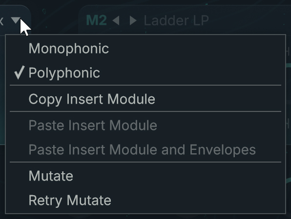 |
Monophonic/Polyphonic (modules on Main channel only): Switches the insert module between Monophonic and Polyphonic modes.
Copy Insert Module: Copies the settings of the module to the clipboard.
Paste Insert Module: Pastes into the module the settings stored in the clipboard (using the command Copy Insert Module).
Paste Insert Module and Envelopes: Pastes into the module the settings stored in the clipboard (using the command Copy Insert Module), including any envelopes linked to the copied module.
Mutate: Mutates this particular module.
Retry Mutate: Retries a mutation of the module. This entry is available only if you have already triggered a mutation in this session.
The Mutate and Retry Mutate commands use the mutation settings defined in the Mutator section of the Browser page.
Mix panel
Every insert module provides a Mix panel with the following controls:
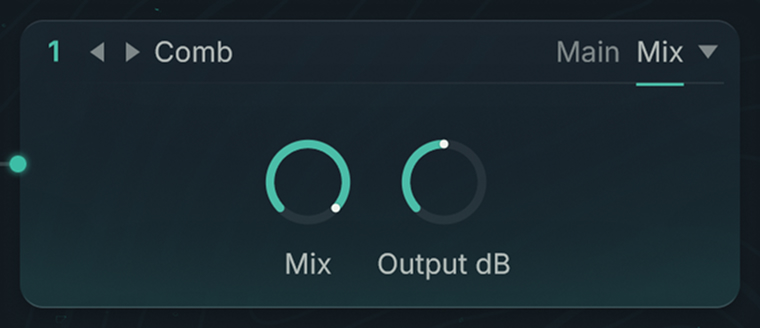 |
Mix: Adjusts the balance between the original signal and the signal processed by the module.
Output dB: Adjusts the output level of the module. This can help compensate for any level changes induced by the module’s processing.
Note
The only exception is the Mix panel of the Ladder Notch module, which contains an additional LP/HP parameter.
Filters
The Filter modules provide a number of filters to work with.
Feedback loop and Feedback panel
The LPF Feedback, Allpass Feedback, and Supercomb Filter modules provide a feedback loop. This feedback loop allows to send a portion of the filter’s output back to its own input while adding an extra processing on the way.
The feedback loop settings are located on the FB panel (Feedback) panel:
 |
Note
The feedback loop is built inside the resonance loop of the Filters. Therefore, the amount of signal sent in the feedback loop is also affected by the Feedback parameter of the Main panel for these modules, which controls the filter resonance.
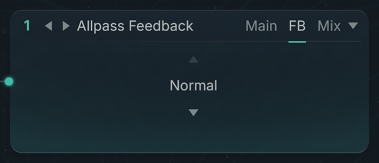
The Feedback panel contains a Feedback Mode menu selecting the feedback mode. If Normal is selected, no additional processing takes place within the feedback loop. The three other modes available in the Feedback Mode menu are described below.
Wave Shaper feedback mode
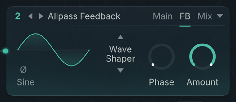 |
When this mode is selected, the signal in the feedback loop is processed by a mini Waveshaper module. The parameters in the FB panel are the same as in the Waveshaper module except for the following differences:
A Phase Inverter button is available below the Mini Waveform.
The Input control from the Waveshaper module is replaced with an Amount control adjusting the proportion of signal processed by the Waveshaper in the feedback loop.
Freq Shift feedback mode
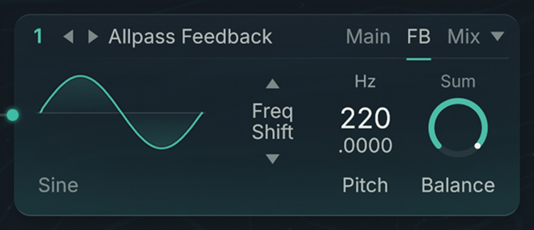 |
When this mode is selected, the signal in the feedback loop is processed by a mini Freq Shift module. The parameters in the FB panel are the same as in the Freq Shift module except that the Feedback control from the Freq Shift module is replaced with a Balance control adjusting the proportion of signal processed by the Freq Shift.
Ring Mod feedback mode
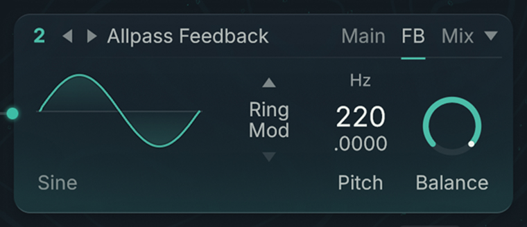 |
When this mode is selected, the signal in the feedback loop is processed by a mini Ringmod module. The parameters in the FB panel are the same as in the Ringmod module.
Ladder LP
This lowpass filter is based on the classic ladder circuit used in early synthesizers.
The Main panel contains the following parameters:
Slope menu: Selects the slope gradient of the signal attenuation in dB per octave. A value of -12 dB/octave means that the filter dampens a signal one octave higher by 12 dB more. The available values are -6 dB, -12 dB, -18 dB, and -24 dB.
Frequency control and Frequency menu: The Frequency control adjusts the cutoff frequency in semitones (Transpose) or in Hertz (Hz) depending on the unit selected in the Frequency menu above.
Resonance control (Res): Adjusts the resonance at the cutoff frequency.
Ladder HP
This highpass filter is based on the classic ladder circuit used in early synthesizers.
The Main panel contains the following parameters:
Slope menu: Selects the slope gradient of the signal attenuation in dB per octave. A value of -12 dB/octave means that the filter dampens a signal one octave lower by 12 dB more. The available values are -6 dB, -12 dB, -18 dB, and -24 dB.
Frequency control and Frequency menu: The Frequency control adjusts the cutoff frequency in semitones (Transpose) or in Hertz (Hz) depending on the unit selected in the Frequency menu above.
Resonance control (Res): Adjusts the resonance at the cutoff frequency.
Ladder BP
This bandpass filter is based on the classic ladder circuit used in early synthesizers.
The Main panel contains the following parameters:
Slope menu: Selects the slope gradient of the signal attenuation around the cutoff frequency, in dB per octave. A value of -12 dB/octave means that a signal one octave further away from the cutoff frequency would be dampened by 12 dB more. The available values are -6 dB and -12 dB.
Frequency control and Frequency menu: The Frequency control adjusts the cutoff frequency in semitones (Transpose) or in Hertz (Hz) depending on the unit selected in the Frequency menu above.
Resonance control (Res): Adjusts the resonance at the cutoff frequency.
Ladder Notch
A notch filter is the opposite of a bandpass filter: It rejects a particular frequency band. This notch filter is based on the classic ladder circuit used in early synthesizers. It combines a lowpass filter and a highpass filter.
The Main panel contains the following parameters:
Slope menu: Selects the slope gradient of the signal attenuation around the cutoff frequency, in dB per octave. A value of -12 dB/octave means that a signal one octave closer to the cutoff frequency would be dampened by 12 dB more. The available values are -6 dB and -12 dB.
Frequency control and Frequency menu: The Frequency control adjusts the cutoff frequency in semitones (Transpose) or in Hertz (Hz) depending on the unit selected in the Frequency menu above.
Resonance control (Res): Adjusts the resonance at the cutoff frequency.
Bandwidth: Adjusts the width of the frequency band that is rejected.
The Mix panel contains the following parameters:
LP/HP: Adjusts the balance between the lowpass and highpass filter outputs.
Mix: Adjusts the balance between the original signal and the signal processed by the module.
Output dB: Adjusts the output level of the module. This can help compensate for any level changes induced by the module’s processing.
LPF Feedback
This lowpass filter is equipped with a feedback loop.
The Main panel contains the following parameters:
Slope menu: Selects the slope gradient of the signal attenuation, expressed as a number of poles. The available values are 2-Pole, 4-Pole, and 8-Pole, which correspond to -12 dB/octave, -24 dB/octave, and -48 dB/octave, respectively. A value of -12 dB/octave means that the filter dampens a signal one octave higher by 12 dB more.
Frequency control and Frequency menu: The Frequency control adjusts the cutoff frequency in semitones (Transpose) or in Hertz (Hz) depending on the unit selected in the Frequency menu above.
Feedback: Adjusts the level of the signal sent into the feedback loop, which affects the resonance at the cutoff frequency. This control is bipolar: At its default middle position (zero), the resonance is at minimum. From this middle position, turning the Feedback knob in either direction will increase the resonance of the filter.
The parameters of the FB panel (Feedback) let you configure the additional processing in the feedback loop. They are described in Feedback loop and Feedback panel.
Allpass Feedback
Allpass filters allow all frequencies to pass through the output with similar strength, but modify the phase of the signal. Allpass filters are useful for creative filtering as they can easily produce phasing or resonating effects. With allpass filters, the number of poles define the number of peaks in the frequency spectrum of the filtered signal. With high resonance values, an 8-pole allpass filter can sound similar to a bell.
This allpass filter is equipped with a feedback loop.
The Main panel contains the following parameters:
Slope menu: Selects the slope gradient of the signal attenuation, expressed as a number of poles. The available values are 2-Pole, 4-Pole, and 8-Pole.
Frequency control and Frequency menu: The Frequency control adjusts the cutoff frequency in semitones (Transpose) or in Hertz (Hz) depending on the unit selected in the Frequency menu above.
Feedback: Adjusts the level of the signal sent into the feedback loop, which affects the resonance at the cutoff frequency. This control is bipolar: At its default middle position (zero), the resonance is at minimum. From this middle position, turning the Feedback knob in either direction will increase the resonance of the filter.
The parameters of the FB panel (Feedback) let you configure the additional processing in the feedback loop. They are described in Feedback loop and Feedback panel.
Supercomb
The Supercomb filter is a Comb Filter equipped with a feedback loop and a tonal control borrowing characteristics from the Resonators and Pipe effects.
The Supercomb provides the following panels:
The Main panel is the same as in the Comb Filter.
The FB panel (Feedback) specifies the processing taking place in the feedback loop.
The Tone panel lets you adjust the tone of the filter.
Main panel
The Main panel contains the following parameters:
Frequency control and Frequency menu: The Frequency control adjusts the cutoff frequency in semitones (Transpose) or in Hertz (Hz) depending on the unit selected in the Frequency menu above.
Feedback: Adjusts the amplification factor of the delayed signal. Higher values induce steeper frequency peaks and cancellations.
Feedback panel
The parameters of the FB panel (Feedback) let you configure the additional processing in the feedback loop. They are described in Feedback loop and Feedback panel.
Tone panel
The Tone panel contains the following parameters:
Tone Mode selector: Selects from different resonance modes. The higher the feedback is turned up, the more pronounced the effect is. The Tone mode changes the color of the decay.
Tone: This controls affects the sound differently according to the mode selected in the Tone Mode menu above. It is not available in Clean mode.
HP: Low frequency damping. Low frequencies decay faster as this control is turned up.
LP: High frequency damping. High frequencies decay faster as this is turned down. This control is useful for a more natural resonance.
Position: Controls the ratio of the delay taps, as described for the Comb Filter. This control changes the color of the filter.
Tip
Don’t hesitate to play with these controls to understand how they affect the sound. In particular, you can modulate the Position parameter to get nice effects!
Mix panel
Comb
Comb filters change the sound by delaying the signal by a few milliseconds and mixing the delayed signal with the original. As a result, the level of certain frequencies may be raised or attenuated in the filtered signal.
Tip
Effects such as the phaser and the flanger use this phenomenon. By modulating the Comb’s parameters, you can quickly produce a nice flanging effect.
The Main panel contains the following parameters:
Frequency control and Frequency menu: The Frequency control adjusts the cutoff frequency in semitones (Transpose) or in Hertz (Hz) depending on the unit selected in the Frequency menu above.
Feedback: Adjusts the amplification factor of the delayed signal. Higher values induce steeper frequency peaks and cancellations.
Cloud
The Cloud filter is a reduced version of the Aetherizer effect, a granular delay with multiple feedback and tone controls. It inherits the most important parameters of the Aetherizer.
The Cloud filter does not have the panels usually found in other filter types. Instead, it provides the three following panels:
The Grain panel controls the grain cloud.
The Tone panel configure a filter.
The Mix panel adjusts the mix between the dry and processed signals and the level of the output signal.
Grain panel
The Grain panel contains the following parameters:
HD switch: Activates or deactivates the High Density mode. In High Density mode the grain cloud can reach higher densities, which results in a both fuller and more polished sound.
Rate Hz: Defines the number of grains created during one second.
Transpose: Sets the global transposition of the grains.
Delay ms: Adjusts the pre-delay time involved in the grain creation,, in milliseconds.
Each parameter also has its own dedicated Jitter slider on the right that lets the value randomly deviate from the defined setting.
Tone panel
The Tone panel contains the following parameters:
Filter on/off switch: Activates/deactivates the Cloud's internal filter. The remaining parameters on the panel are visible only if this Filter switch is turned on.
Frequency: Defines the cutoff frequency of the internal filter.
Resonance: Adjusts the resonance of the internal filter.
Quantize menu: Activates/deactivates the filter quantization, and selects a quantization mode. The filter quantization distributes the possible cutoff frequencies over one of the scales available in the menu.
Transpose (all modes except Vowel and Quantize Off): Adjusts the base pitch of the scale on which the cutoff frequencies are quantized.
Vowel Mix (Vowel mode only): Lets you morph between different vowels.
The Frequency, Resonance, and Transpose / Vowel Mix parameters also have their own dedicated Jitter sliders on the right that let the values randomly deviate from the defined settings.
Mix panel
You can find more information on all these parameters in Aetherizer.
LPF (Legacy)
This is the lowpass filter available in previous versions of Absynth.
The Main panel contains the following parameters:
Slope menu: Selects the slope gradient of the signal attenuation in dB per octave. A value of -12 dB/octave means that the filter dampens a signal one octave higher by 12 dB more. The available values are -6 dB, -12 dB, and -24 dB.
Frequency control and Frequency menu: The Frequency control adjusts the cutoff frequency in semitones (Transpose) or in Hertz (Hz) depending on the unit selected in the Frequency menu above.
Resonance control (Res): Adjusts the resonance at the cutoff frequency.
HPF (Legacy)
This is the highpass filter available in previous versions of Absynth.
The Main panel contains the following parameters:
Slope menu: Selects the slope gradient of the signal attenuation in dB per octave. A value of -12 dB/octave means that the filter dampens a signal one octave lower by 12 dB more. The available values are -6 dB and -12 dB.
Frequency control and Frequency menu: The Frequency control adjusts the cutoff frequency in semitones (Transpose) or in Hertz (Hz) depending on the unit selected in the Frequency menu above.
Resonance control (Res): Adjusts the resonance at the cutoff frequency.
BPF (Legacy)
This is the bandpass filter available in previous versions of Absynth.
The Main panel contains the following parameters:
Frequency control and Frequency menu: The Frequency control adjusts the cutoff frequency in semitones (Transpose) or in Hertz (Hz) depending on the unit selected in the Frequency menu above.
Resonance control (Res): Adjusts the resonance at the cutoff frequency.
Notch (Legacy)
This is the notch filter available in previous versions of Absynth.
The Main panel contains the following parameters:
Frequency control and Frequency menu: The Frequency control adjusts the cutoff frequency in semitones (Transpose) or in Hertz (Hz) depending on the unit selected in the Frequency menu above.
Resonance control (Res): Adjusts the resonance at the cutoff frequency.
Bandwidth: Adjusts the width of the frequency band that is rejected.
Modulators
The Modulator modules use a built-in oscillator to modulate the incoming signal. Two Modulators are available: Freq Shift and Ringmod.
Freq Shift
The Freq Shift module produces a frequency shift by using a feedback loop. From a functional point of view, the frequency shift resembles the ring modulation, and it can also bring similar sonic results. From a technical point of view, though, there is the following difference: While the Ringmod module produces frequency sums as well as frequency differences, the Freq Shift module limits itself to either frequency sums or differences. Practically, this means that the Freq Shift sounds are subtler and easier to control than the Ringmod sounds. Because there is no interference between the sum and the difference frequencies, the Freq Shift frequently sounds cleaner than the Ringmod in situations involving complex input signals (for example, samples or saw tooth waveforms).
Note
Frequency shifting is not equivalent to pitch shifting. A pitch shifter multiplies the frequencies of the input signal by a certain factor: As a result, the harmonic relations between the frequencies are maintained. By contrast, a frequency shifter adds a certain value to the frequencies of the input signal, which alters the harmonic relations the input signal may contain.
The Main panel contains the following parameters:
Mini Waveform: Shows the shape and the name of the loaded waveform. If a Morph waveform is loaded, you can click the shape and drag your mouse vertically to morph the waveform. Clicking the waveform name opens the Waveform selector and lets you choose another waveform.
Pitch menu and control: These controls let you to define the oscillator’s frequency as a transposition of the played note (Transpose), as a relationship with the played note (Ratio), as a fixed frequency (Hz), or as a fixed MIDI note number (Note).
Note
The Pitch menu and control are similar to the Frequency menu and control available in the Oscillator modules. You can find more information in Frequency menu and control.
Sum/Difference switch: With the switch set to Sum, the Freq Shift module produces frequency sums, otherwise it produces frequency differences.
Feedback: Adjusts the amount of feedback. A higher feedback generates a richer sound.
Tip
A light detuning between the input signal and the Modulator signal, combined with a moderate Feedback value, can induce a nice phasing effect. Very low Frequency values (e.g., 1 Hz) can lead to similar effects.
Ringmod
The Ringmod module produces ring modulation and is similar to the Ringmod Oscillator from the source modules. The amplitudes of the input signal and Modulator signal are multiplied with each other.
The Main panel of the Ringmod module contains the following parameters:
Mini Waveform: Shows the shape and the name of the loaded waveform. If a Morph waveform is loaded, you can click the shape and drag your mouse vertically to morph the waveform. Clicking the waveform name opens the Waveform selector and lets you choose another waveform.
Pitch menu and control: These controls let you to define the oscillator’s frequency as a transposition of the played note (Transpose), as a relationship with the played note (Ratio), as a fixed frequency (Hz), or as a fixed MIDI note number (Note).
Note
The Pitch menu and control are similar to the Frequency menu and control available in the Oscillator modules. You can find more information in Frequency menu and control.
Balance: Adjusts the balance between the input signal and the modulated signal.
Waveshaper
The Waveshaper module uses a waveform to shape an input signal. This idea is used in guitar amplifiers and distortion effects. Waveshaping reacts to the amplitude of the input signal: The sound changes depending on the volume envelope of the oscillator or any other form of oscillator-volume control. Additionally, waveshaping emphasizes phasing and detuning effects in the signal.
You can always use the Waveshaper module when you want to enrich a signal with harmonics. Its action ranges from subtle density to cutting distortion. The Waveshaper reacts to changes in the amplitude. The level of distortion changes with every fluctuation of the input signal, which generates a very dynamic sound.
The Main panel contains the following parameters:
Mini Waveform: Shows the shape and the name of the loaded waveform. If a Morph waveform is loaded, you can click the shape and drag your mouse vertically to morph the waveform. Clicking the waveform name opens the Waveform selector and lets you choose another waveform.
Input: Adjusts the input level in dB. Increasing this value usually strengthens the distortion. This strengthening is not linear, however, and depends on the selected waveform and the Phase value. You can experiment with different settings to get the sound that you want.
Phase: Adjusts the phase of the waveform. This parameter has an extreme effect on the sound, especially when working with complex waveforms, since these will be very sensitive to phase changes.
Tip
If you want to make yourself more comfortable with the effect of the Waveshaper, you could create a new waveform for the Waveshaper and work on it in the Spectrum view of the Wave page while listening to the results.
Effect modules
The effect modules can be inserted in the third and rightmost position in the Main channel at the bottom of the Patch page. This makes them the last processing in the signal path of Absynth. The effect modules host the effects configured in the Effect page.
You can switch between the available effect modules by using the Type selector at the top of the modules:
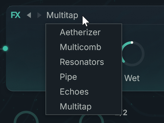 |
The Main panel of the effect modules shows the most important parameters of the respective effects. These parameters vary with each effect, you can find their description in Effect page. You can click the effect thumbnail in the left part of the Main panel to jump directly to that effect in the Effect page.
The Mix panel of the effect modules contains two knobs: Dry and Wet. These knobs let you adjust the balance between the unprocessed signal (Dry) and the processed signal (Wet). They correspond to the Dry and Wet knobs in the Input Mix section of the Effect page.